Stihl FS 510 C-M Instruction Manual - Page 22
Mounting the Handlebar
 |
View all Stihl FS 510 C-M manuals
Add to My Manuals
Save this manual to your list of manuals |
Page 22 highlights
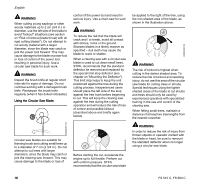
3BA007 KN English 5 8 4 3 3BA005 KN 2BA001 KN 3 Handlebar for machines used mainly for sawing, but also for mowing and brushcutting. The machine is supplied with the clamp moldings (4) mounted to the handlebars (2, 3). N Do not change the position of the clamp moldings on the handlebar until it is mounted on the handle support. The mounting procedure is the same for both types of handlebar. Therefore, the following description only explains how to mount handlebar (2). Mounting the Handlebar To assemble the rotating handlebar support, the clamps must be fitted with a spring and fastened to the handlebar support on the machine. N Use the spring (5) from the parts kit supplied with the machine. N Push the spring (5) into the lower clamp molding (6). 4 2 7 N Position the clamp moldings (4) with handlebar (2) on the handle support (7). N Do not rotate the handlebar in the clamp moldings. 4900BA002 KN N Raise the grip of the wing screw (8) to the upright position. N Rotate the wing screw counterclockwise and tighten it only moderately. 8 5 7 3BA008 KN N Position wing screw (8) in threaded insert in handle support (7) - against pressure of spring (5). 3BA0009 KN 9 6 10 7 N Position the clamp moldings so that the tabs (9) on the lower clamp molding (6) line up with the slots (10) in the handle support (7). 20 FS 510 C, FS 560 C
-
 1
1 -
2
-
3
-
4
-
5
-
6
-
7
-
8
-
9
-
10
-
11
-
12
-
13
-
14
-
15
-
16
-
 17
17 -
 18
18 -
 19
19 -
 20
20 -
 21
21 -
 22
22 -
 23
23 -
 24
24 -
 25
25 -
 26
26 -
 27
27 -
28
-
29
-
30
-
31
-
32
-
33
-
34
-
35
-
36
-
37
-
38
-
39
-
40
-
41
-
42
-
43
-
44
-
45
-
46
-
47
-
48
-
49
-
50
-
51
-
52
-
53
-
54
-
55
-
56
-
57
-
58
-
59
-
60
-
61
-
62
-
63
-
64
-
65
-
66
-
67
-
68
-
69
-
70
-
71
-
72
-
73
-
74
-
75
-
76
-
77
-
78
-
79
-
80
-
81
-
82
-
83
-
84
-
85
-
86
-
87
-
88
-
89
-
90
-
91
-
92
-
93
-
94
-
95
-
96
-
97
-
98
-
99
-
100
-
101
-
102
-
103
-
104
-
105
-
106
-
107
-
108
-
109
-
110
-
111
-
112
-
113
-
114
-
115
-
116
-
117
-
118
-
119
-
120
-
121
-
122
-
123
-
124
 |
 |
