Sharp XG-P610X XG-P610X Operation Manual - Page 35
Basic Operation
 |
View all Sharp XG-P610X manuals
Add to My Manuals
Save this manual to your list of manuals |
Page 35 highlights
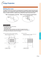
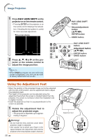
GEOMETRIC ADJUSTMENT 1 Press KEYSTONE on the pro- jector or on the remote control repeatedly until "GEOMETRIC ADJUSTMENT" is displayed. 2 Press the buttons below to ad- just the position, size or focus of the projected image. • Match screen's four sides to green test pattern. • Pressing ', ", \ or | on the projector or H&V LENS SHIFT on the remote control allows you to shift the lens. • Pressing ZOOM +/- on the projector or on the remote control allows you to adjust the projected image size. • Pressing FOCUS +/- on the projector or on the remote control allows you to adjust the focus. 3 Press ENTER on the projector or on the remote control. 4 Press ', ", \ or | to move the position for the upper left of the image. • Move the upper left of the yellow frame onto the upper left of the screen. 5 Press ENTER to set the posi- tion. 6 Repeat the same procedure with the positions for the upper right, lower right and lower left of the image. • At this time, pressing UNDO on the projector or on the remote control returns to the previous screen. • Before correcting the upper left of the image, pressing UNDO returns to the reset confirmation screen. • When the position of the lower left is set, the correction is made and the display disappears. • If the message "Can not correct." is displayed, step 2 may have been performed incorrectly. In this case, go back to step 2 and try the procedure again. ▼On-screen display Geometric Adjustment Upper Left Upper Right Lower Right Lower Left -33 Basic Operation
-
 1
1 -
2
-
3
-
4
-
5
-
6
-
7
-
8
-
9
-
10
-
11
-
12
-
13
-
14
-
15
-
16
-
17
-
18
-
19
-
20
-
21
-
22
-
23
-
24
-
25
-
26
-
27
-
28
-
29
-
 30
30 -
 31
31 -
 32
32 -
 33
33 -
 34
34 -
 35
35 -
 36
36 -
 37
37 -
 38
38 -
 39
39 -
 40
40 -
41
-
42
-
43
-
44
-
45
-
46
-
47
-
48
-
49
-
50
-
51
-
52
-
53
-
54
-
55
-
56
-
57
-
58
-
59
-
60
-
61
-
62
-
63
-
64
-
65
-
66
-
67
-
68
-
69
-
70
-
71
-
72
-
73
-
74
-
75
-
76
-
77
-
78
-
79
-
80
-
81
-
82
-
83
-
84
-
85
-
86
 |
 |
