Sharp R-410FW Service Manual - Page 27
Control Panel Assembly Removal, Positive Lock, Connector No-case Type Removal, Oven Lamp And Lamp
 |
View all Sharp R-410FW manuals
Add to My Manuals
Save this manual to your list of manuals |
Page 27 highlights
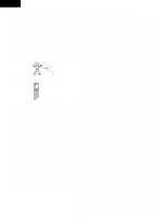
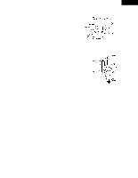
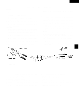
OVEN LAMP AND LAMP SOCKET REMOVAL 1. Disconnect the power supply cord and remove outer case. 2. Open the door and block it open. 3. Discharge high voltage capacitor. 4. Remove the oven lamp from the oven lamp socket. 5. Pull the wire leads from the oven lamp socket by pushing the terminal hole of the oven lamp socket with the small flat type screw driver. 6. Remove the oven lamp socket from the magnetron duct by turning the socket counterclockwise. 7. Remove the oven lamp from the socket by turning the oven lamp. 8. Now, the oven lamp and the oven lamp socket are free. Figure C-1. Oven lamp socket POSITIVE LOCK® CONNECTOR (NO-CASE TYPE) REMOVAL 1. Disconnect the power supply cord, and then remove outer case. 2. Open the door and block it open. 3. Discharge high voltage capacitor. 4. Push the lever of positive lock® connector. 5. Pull down on the positive lock® connector. R-410FK R-410FW CAUTION: WHEN CONNECTING THE POSITIVE LOCK® CONNECTORS TO THE TERMINALS, CONNECT THE POSITIVE LOCK® SO THAT THE LEVER FACES YOU. Figure C-2. Positive lock® connector CONTROL PANEL ASSEMBLY REMOVAL 1. Disconnect the power supply cord and then remove outer case. 2. Open the door and block it open. 3. Discharge high voltage capacitor. 4. Disconnect the wire leads from panel components. 5. Remove the one (1) screw holding the control panel assembly to the oven cavity front plate. 6. Slide the control panel assembly upward and remove it. 7. Now, individual components can be removed. NOTE: 1. Before attaching a new key unit, wipe off remaining adhesive on the control panel frame surfaces completely with a soft cloth soaked in alcohol. 2. When attaching the key unit to the control panel frame, adjust the upper edge and right edge of the key unit to the correct position of control panel frame. 3. Place the key unit firmly to the control panel frame by rubbing with soft cloth not to scratch. GRAPHIC SHEET AND MEMBRANE SWITCH REPLACEMENT Removal 1. Disconnect the power supply cord and then remove outer case. 2. Open the door and block it open. 3. Discharge high voltage capacitor. 4. Remove the control panel assembly, referring to chapter of CONTROL PANEL ASSEMBLY REMOVAL. 5. Remove the three (3) screws holding the control unit to the control panel frame. And remove the control unit by releasing from tabs. 6. Remove the rubber connector from the long slit on the control panel frame. 7. Remove the graphic sheet from the control panel frame. (*See special note) 8. Remove away the membrane switch from the control panel frame. (*See special note) 25
-
 1
1 -
2
-
3
-
4
-
5
-
6
-
7
-
8
-
9
-
10
-
11
-
12
-
13
-
14
-
15
-
16
-
17
-
18
-
19
-
20
-
21
-
 22
22 -
 23
23 -
 24
24 -
 25
25 -
 26
26 -
 27
27 -
 28
28 -
 29
29 -
 30
30 -
 31
31 -
 32
32 -
33
-
34
-
35
-
36
-
37
-
38
-
39
-
40
-
41
-
42
-
43
-
44
 |
 |
