Sharp R-231NW Service Manual - Page 26
] Positive Lock Connector No-case Type Removal, 7] Control Panel Assembly Removal, 8] Graphic Sheet
 |
View all Sharp R-231NW manuals
Add to My Manuals
Save this manual to your list of manuals |
Page 26 highlights
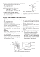
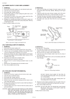
R-231NW [6] POSITIVE LOCK CONNECTOR (NO-CASE TYPE) REMOVAL 1. Disconnect the power supply cord, and remove outer case. 2. Open the door and block it open. 3. Discharge high voltage capacitor. 4. Push the lever of positive lock® connector. 5. Pull down on the positive lock® connector. CAUTION: WHEN CONNECTING THE POSITIVE LOCK® CONNECTORS TO THE TERMINALS, INSTALL THE POSITIVE LOCK® SO THAT THE LEVER FACES YOU. [7] CONTROL PANEL ASSEMBLY REMOVAL Positive lock® connector Lever Figure C-1. positive lock® connector Terminal 1 Push 2 Pull down 1. Disconnect the power supply cord and remove outer case. 2. Open the door and block it open. 3. Discharge high voltage capacitor. 4. Disconnect the leads from the control unit. 5. Remove the one (1) screw holding the control panel to the front plate of the oven cavity. 6. Now, the control panel assembly is free. [8] GRAPHIC SHEET AND MEMBRANE SWITCH REPLACEMENT 1. REMOVAL 1. Disconnect the power supply cord and then remove outer case. 2. Open the door and block it open. 3. Discharge high voltage capacitor. 4. Remove the control panel assembly, referring to chapter of CONTROL PANEL ASSEMBLY REMOVAL. 5. Remove the two (2) screws holding the control unit to the control panel frame. And remove the control unit. 6. Remove the rubber connector from the long slit on the control panel frame. 7. Tear away the graphic sheet from the control panel frame. 8. Tear away the membrane switch from the control panel frame. 2. REINSTALL 1. Remove remaining adhesive on the control panel frame surfaces with a soft cloth soaked in alcohol. 2. Tear the backing paper from the new membrane switch. 3. Insert the ribbon cable of the membrane switch into the slit of the control panel frame. 4. Adjust the upper edge and right edge of the membrane switch to the small depression on the surface of the control panel frame. 5. Attach the membrane switch to the control panel frame by rubbing with a soft cloth not to scratch. 6. Tear the backing paper from the new graphic sheet. 7. Adjust the upper edge and left edge of the graphic sheet to the large depression on the surface of the control panel frame. 8. Attach the graphic sheet to the control panel frame by rubbing with a soft cloth not to scratch. 9. Tear the small backing paper from the ribbon cable of the membrane switch. 10. Attach the ribbon cable to the control panel frame rear side. 11. Place the edge of the membrane switch's ribbon cable on the lower portion of the liquid crystal display. 12. Insert the rubber connector into the long slit on the control panel frame. 13. Reinstall the control unit to the control panel frame with the two (2) screws. NOTE: Do not contact the contact surface of the ribbon cable (edge) and the rubber connector directly with your fingers. This is to avoid oxidized. If display digits are missing or scrambled, remove control unit and clean contact surface with alcohol. After cleaning, do not attach the rubber connector until alcohol dries up. Do not use alcohol or solution to clean the rubber connector. Make sure that there is no trash or foreign substance on contact surface of the rubber connector. Large depression Small backing paper Control panel frame Slit Liquid crystal display Long slit Ribbon cable Graphic sheet Ribbon cable of membrane switch Small depression Membrane switch Figure C-2. Graphic Sheet and Membrane Switch Replacement Control panel frame (Rear side) Contact surface Rubber connector 11 - 3
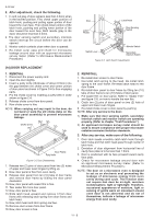
-
 1
1 -
2
-
3
-
4
-
5
-
6
-
7
-
8
-
9
-
10
-
11
-
12
-
13
-
14
-
15
-
16
-
17
-
18
-
19
-
20
-
 21
21 -
 22
22 -
 23
23 -
 24
24 -
 25
25 -
 26
26 -
 27
27 -
 28
28 -
 29
29 -
 30
30 -
 31
31 -
32
-
33
-
34
-
35
-
36
-
37
-
38
-
39
-
40
-
41
 |
 |
