Sharp LC-13AV6U Service Manual - Page 12
Precautions at the time of the side-Bback service of main and sub unit., Extension Cable 8-pin R/C
 |
View all Sharp LC-13AV6U manuals
Add to My Manuals
Save this manual to your list of manuals |
Page 12 highlights
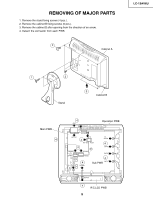
LC-13AV6U » Precautions at the time of the side-B(back) service of main and sub unit. 1. Remove the FPC for connection between Main unit (SC1701) and LCD panel (CN1), and connect the extended cable (QCNW-C458WJQZ) for service. 2. Remove only SC1201 side of the lead from between Main unit (SC1201) and Sub unit (P7301), and connect the extended cable (QCNW-C461WJQZ) for service. 3. Remove only SC2001 side of the lead from between Main unit (SC2001) and Sub unit (P3901), and connect the extended cable (QCNW-C461WJQZ) for service. 4. Remove only SC2002 side of the lead from between Main unit (SC2002) and Sub unit (P3902), and connect the extended cable (QCNW-D402WJQZ) for service. 5. Remove the FFC for connection between Main unit (SC2003) and Operation unit (SC4201), and connect the extended cable (QCNW-D444WJQZ) for service. 6. Remove the FFC for connection between Sub unit (SC3601) and R/C, LED unit (SC4101), and connect the extended cable (QCNW-D445WJQZ) for service. 7. Remove the PWB unit fixing screws (main unit: 2 pcs., sub unit: 2 pcs.) Main PWB CN1 SC4201 Operation PWB 1 SC1701 3 5 SC2003 2 SC1201 P7301 4 SC2001 SC2002 P3901 P3902 7 SC3601 6 SC4101 R/C, LED PWB Sub PWB Sub PWB (Side B) Main PWB (Side B) Step 1 2 3 4 5 6 Part No. QCNW-C458WJQZ QCNW-C461WJQZ QCNW-C461WJQZ QCNW-D402WJQZ QCNW-D444WJQZ QCNW-D445WJQZ Description Extension Cable 80-pin Main (SC1701)-LCD panel (CN1) Extension Cable 15-pin Main (SC1201)-Sub (P7301) Extension Cable 15-pin Main (SC2001)-Sub (P3901) Extension Cable 23-pin Main (SC2002)-Sub (P3902) Extension Cable 5-pin Operation (SC4201)-Main (SC2003) Extension Cable 8-pin R/C, LED (SC4101)-Sub (SC3601) 12
-
 1
1 -
2
-
3
-
4
-
5
-
6
-
 7
7 -
 8
8 -
 9
9 -
 10
10 -
 11
11 -
 12
12 -
 13
13 -
 14
14 -
 15
15 -
 16
16 -
 17
17 -
18
-
19
-
20
-
21
-
22
-
23
-
24
-
25
-
26
-
27
-
28
-
29
-
30
-
31
-
32
-
33
-
34
-
35
-
36
-
37
-
38
-
39
-
40
-
41
-
42
-
43
-
44
-
45
-
46
-
47
-
48
-
49
-
50
-
51
-
52
-
53
-
54
-
55
-
56
-
57
-
58
-
59
-
60
-
61
-
62
-
63
-
64
-
65
-
66
-
67
 |
 |
