Sharp CD-E33 Service Manual - Page 38
IC401 VHiMN6627482W: Servo/Signal Control MN6627482W 2/2
 |
View all Sharp CD-E33 manuals
Add to My Manuals
Save this manual to your list of manuals |
Page 38 highlights
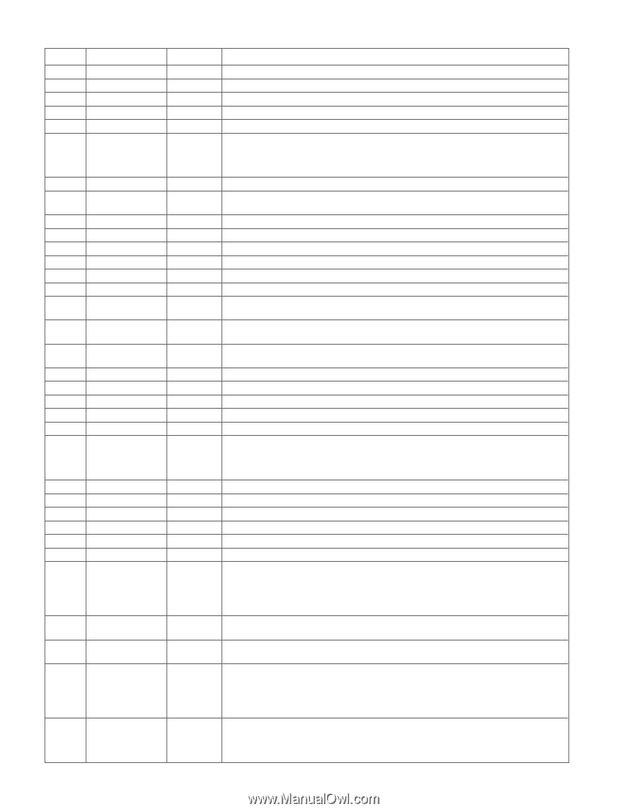
CD-E300 CD-E33 IC401 VHiMN6627482W: Servo/Signal Control (MN6627482W) (2/2) Pin No. Terminal Name Input/Output Function 47 DSLF Input/Output DSL loop filter terminal. 48 PLLF Input/Output PLL loop filter terminal. 49 VCOF Input/Output VCO loop filter terminal. 50 AVDD2 Input Analog circuit power supply. (DSL, PLL and DA output sections for AD) 51 AVSS2 Input Analog circuit GND. (DSL, PLL and DA output sections for AD) 52* EFM, CK384 Output · IOSEL=H: EFM signal output. · IOSEL=L: X-tal system 16.9344 MHz clock output. Signal processing system: 384fs output. (VCO clock for jitter-free operation) (X-tal system or signal processing system can be selected by the command.) 53 PCK, DSLB Output PLL extraction clock output or DSL balance output. fPCK-4.3218 MHz 54 VCOF2 Input/Output Loop filter terminal for digital servo 33.8688 MHz creation VCO. X-tal 16.9344 MHz: external circuit is needed. 55* SUBC Output Subcode serial output. CD-TEXT mode 1: TEXT data output. 56* SBCK Input Subcode serial output clock input. CD-TEXT mode 1: TEXT data read clock input 57 VSS Input Oscillation circuit GND. 58 X1 Input Oscillation circuit input terminal. f=16.9344 MHz, 33.8688 MHz 59 X2 Output Oscillation circuit output terminal. f=16.9344 MHz, 33.8688 MHz 60 VDD Input Oscillation circuit power supply. 61* BYTCK, TRVSTP Output IOSEL=H: byte clock signal output. IOSEL=L: traverse STOP signal output. H: STOP Mode 62* GIO1, /CLDCK Output Default: general purpose I/O port. Command execution: terminal for subcode frame clock signal output. (fCLDCK=7.35 kHz) 63* GIO2, FCLK Output Default: general purpose I/O port. Command execution: crystal frame clock signal output. (fFCLK=7.35 kHz) 64* IPFLAG Output Interpolation flag signal output. H: Interpolation 65* FLAG Output Flag signal output. 66* CLVS Output Output for spindle servo phase synchronization signal. H: CLV, L: Rough servo 67* CRC Output Default: output for subcode CRC check results. H: OK, L: NG 68* DEMPH Output Demphasis detection signal output. H: ON 69* RESY, FLAG6 Output IOSEL= H: resync signal RESY output for frame synchronization. H: Synchronization, L: Synchronization lost IOSEL=L: RAM address reset signal for error correct deinterleave. FLAG 6 output L: Address reset 70 IOSEL Input Mode switch terminal. 71 /TEST Input Test terminal. Normal: H 72 AVDD1 Input Analog circuit power supply. (Audio output section (for both Lch and Rch)) 73 OUTL Output Lch audio output. 74 AVSS1 Input Analog circuit GND. (Audio output section (for both Lch and Rch)) 75 OUTR Output Rch audio output. 76 RSEL, GIO3 Input Default: RF signal polarity specification terminal. Brightness H: RESEL=H Brightness L: RESEL=L Command execution: general purpose I/O port. RF signal polarity can be specified by command. CD-TEXT mode 1 or 2: TEXT data read enabling signal (DQSY) output 77 CSEL Input Oscillation frequency specification terminal. H: Oscillation frequency=33.8688 MHz L: Oscillation frequency=16.9344 MHz 78 PSEL Input IOSEL=H: test terminal. (Normal: L) IOSEL=L: SRDATA input. 79 MSEL Input IOEL=H: SMCK terminal output, frequency switch terminal. H: SMCK=8.4672 MHz L: SMCK=4.2336 MHz IOSEL=L: LRCK input H: Lch data, L: Rch data SMCK=4.2336 MHz fixed 80 SSEL Input IOSEL=H: switch terminal for SUBQ terminal output mode. H: Q code buffer mode L: CLDCK synchronization mode IOSEL=L: BCLK input Q code buffer mode fixed In this unit, the terminal with asterisk mark (*) is (open) terminal which is not connected to the outside. - 38 -
-
 1
1 -
2
-
3
-
4
-
5
-
6
-
7
-
8
-
9
-
10
-
11
-
12
-
13
-
14
-
15
-
16
-
17
-
18
-
19
-
20
-
21
-
22
-
23
-
24
-
25
-
26
-
27
-
28
-
29
-
30
-
31
-
32
-
 33
33 -
 34
34 -
 35
35 -
 36
36 -
 37
37 -
 38
38 -
 39
39 -
 40
40 -
 41
41 -
 42
42 -
 43
43 -
44
-
45
-
46
-
47
-
48
-
49
-
50
-
51
-
52
 |
 |