Sanyo PLC-WM5500/L Owners Manual - Page 76
Menu Tree, Computer Input/HDMI Input/Video Input, Computer Input
 |
View all Sanyo PLC-WM5500/L manuals
Add to My Manuals
Save this manual to your list of manuals |
Page 76 highlights
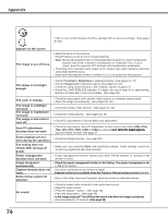
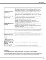
Appendix Menu Tree Computer Input/HDMI Input/Video Input Input Input Input 1 RGB (PC analog) RGB (Scart) HDMI Input 2 Input 3 Video Y, Pb/Cb,Pr/Cr RGB Video Y, Pb/Cb,Pr/Cr S-video Network * * Network will be displayed only when an optional PJ-Net Organizer is attached. Sound Sound Information Information Volume Built-in SP Mute 0-63 On/Off On/Off Input H-sync freq. V-sync freq. Screen Language Lamp status Lamp counter Filter counter Power management Key lock PIN code lock Shutter management Simple mode Remote control SERIAL NO. Computer Input System (1) Mode 1 Mode 10 SVGA 1 SVGA 2 SVGA 3 System displayed in the System Menu varies depending on the input signal. Image adjust Image adjust Contrast Brightness Color temp. Red Green Blue Offset Sharpness Gamma Reset Store 0-63 0-63 XLow Low Mid High Adj 0-63 0-63 0-63 Red/Green/Blue 0-31 0-15 Yes/No Image 1 Image 10 Note: The Menu display varies depending on the input signal. Image select Image select PC adjust PC adjust Dynamic Standard Real Image 1 Image 10 Auto PC adj. Fine sync. Total dots Position H Position V Current mode Clamp Display area - H Display area - V Reset Mode free Store 0-31 Yes/No Mode 1 Mode 10 Quit 76
-
 1
1 -
2
-
3
-
4
-
5
-
6
-
7
-
8
-
9
-
10
-
11
-
12
-
13
-
14
-
15
-
16
-
17
-
18
-
19
-
20
-
21
-
22
-
23
-
24
-
25
-
26
-
27
-
28
-
29
-
30
-
31
-
32
-
33
-
34
-
35
-
36
-
37
-
38
-
39
-
40
-
41
-
42
-
43
-
44
-
45
-
46
-
47
-
48
-
49
-
50
-
51
-
52
-
53
-
54
-
55
-
56
-
57
-
58
-
59
-
60
-
61
-
62
-
63
-
64
-
65
-
66
-
67
-
68
-
69
-
70
-
 71
71 -
 72
72 -
 73
73 -
 74
74 -
 75
75 -
 76
76 -
 77
77 -
 78
78 -
 79
79 -
 80
80 -
 81
81 -
82
-
83
-
84
-
85
-
86
-
87
-
88
-
89
-
90
-
91
-
92
 |
 |
