SanDisk SDSDB-016G-A11 Product Manual
SanDisk SDSDB-016G-A11 Manual
 |
UPC - 619659055639
View all SanDisk SDSDB-016G-A11 manuals
Add to My Manuals
Save this manual to your list of manuals |
SanDisk SDSDB-016G-A11 manual content summary:
- SanDisk SDSDB-016G-A11 | Product Manual - Page 1
SanDisk SD Card Product Manual Version 2.2 Document No. 80-13-00169 November 2004 SanDisk Corporation Corporate Headquarters • 140 Caspian Court • Sunnyvale, CA 94089 Phone (408) 542-0500 • Fax (408) 542-0503 www.sandisk.com - SanDisk SDSDB-016G-A11 | Product Manual - Page 2
SD Card Product Manual SanDisk® Corporation general policy does not recommend the use of its products in life support applications where in a failure or malfunction of the product may directly threaten life or injury. Per SanDisk Terms and Conditions of Sale, the user of SanDisk products in life - SanDisk SDSDB-016G-A11 | Product Manual - Page 3
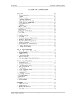
Revision 2.2 SanDisk SD Card Product Manual TABLE OF CONTENTS 1. Introduction 1-1 1.1 General Description 1-1 1.2 Features 1-2 1.3 SD Card Standard 1-2 1.4 Functional Description 1-3 1.5 Independent Flash Technology 1-3 1.6 Defect and Error Management 1-3 1.7 Copyright Protection 1-4 1.8 - SanDisk SDSDB-016G-A11 | Product Manual - Page 4
Revision 2.2 SanDisk SD Card Product Manual 5.5 Data Write 5-3 5.6 Erase and Write Protect Management 5-4 5.7 Read CID/CSD Registers 5-5 5.8 Reset Sequence 5-5 5.9 Clock Control 5-5 5.10 Error Conditions 5-6 5.11 Memory Array Partitioning 5-7 5.12 Card Lock/Unlock 5-7 5.13 Application- - SanDisk SDSDB-016G-A11 | Product Manual - Page 5
SanDisk SD Card Product Manual 1 Introduction 1.1 General Description The SanDisk Secure Digital (SD) Card is a flash-based memory is also available. The physical form factor: pin assignment and data transfer protocol, with some additions, are forward compatible with the SD Card. SanDisk SD Card - SanDisk SDSDB-016G-A11 | Product Manual - Page 6
SanDisk SD Card Product Manual 1.2 Features SanDisk SD Card features include: ►Up to 2-GB of data storage ►SD-protocol compatible ►Supports of memory-field SanDisk SD cards are fully compatible with the SD Card Physical Layer System Specification, Version 1.10. This specification is available - SanDisk SDSDB-016G-A11 | Product Manual - Page 7
flash memory evolves. In other words, systems that support the SD Card today will be able to access future SD cards built with new flash technology without having to update or change host software. 1.6 Defect and Error Management SanDisk future problems. These defect and error management systems - SanDisk SDSDB-016G-A11 | Product Manual - Page 8
Revision 2.2 Chapter 1 - Introduction SanDisk SD Card Product Manual 1.7 Copyright Protection A detailed description of the erase pooling functionality of the SD Card, using NAND memory. The Wear Level command is supported as a NOP operation to maintain backward compatibility with existing software - SanDisk SDSDB-016G-A11 | Product Manual - Page 9
Revision 2.2 Chapter 1 - Introduction SanDisk SD Card Product Manual 1.11 Hot Insertion Support for hot insertion will be required on the host but will be supported through the connector. Connector manufacturers will provide connectors that have power-pins long enough to be powered before contact - SanDisk SDSDB-016G-A11 | Product Manual - Page 10
Revision 2.2 Chapter 1 - Introduction SanDisk SD Card Product Manual • SD Status is stored in 512 bits that are related bits and future specific applications. 1.12.5 Memory Array Partitioning The basic unit of data transfer to/from the SanDisk SD Card is one byte. All data transfer operations - SanDisk SDSDB-016G-A11 | Product Manual - Page 11
Manual Memory Array Partitioning SanDisk SD Memory Card WP Group 0 Sector 1 Bloc Bloc Bloc Bloc k0 k1 k2 kn Sector 2 Sector 3 Sector n WP Group 1 WP Group 2 Protected Area (Copyright Protection) Sector 1 Bloc Bloc Bloc Bloc k0 k1 k2 kn Sector n Table 1-1 Part No. SDSDH-2048 SDSDJ-2048 - SanDisk SDSDB-016G-A11 | Product Manual - Page 12
Chapter 1 - Introduction SanDisk SD Card Product Manual Part No. SDSDJ-32 SDSDB-16 Block Size (Bytes) 512 512 Data Area + Protected size (Blocks) 60,512 29,152 Protected Area2 size (Blocks) 736 352 User Area (Blocks0 59,776 28,800 1.12.6 Read/Write Operations The SD Card supports two read - SanDisk SDSDB-016G-A11 | Product Manual - Page 13
SanDisk SD Card Product Manual 1.12.8 Data Protection in the Flash Card Every sector is protected with an error correction code (ECC). The ECC is generated (in the memory copy and cannot be cleared. The card is available with the copy-bit set or cleared. If Card bus is supported differently in SPI - SanDisk SDSDB-016G-A11 | Product Manual - Page 14
Revision 2.2 Function Card Status Memory Array Partitioning Read/Write Operations Data Transfer Rate Data Protection in the SD Card Erase Write Protection Copyright Protection Chapter 1 - Introduction SanDisk SD Card Product Manual Description In SPI mode, only 16 bits containing errors relevant to - SanDisk SDSDB-016G-A11 | Product Manual - Page 15
Revision 2.2 Chapter 2 - Product Specifications SanDisk SD Card Product Manual 2 Product Specifications 2.1 Overview In this section, all values are defined at an ambient temperature and nominal supply voltage unless otherwise stated. 2.2 System Environmental Specifications Table 2-1 - SanDisk SDSDB-016G-A11 | Product Manual - Page 16
Revision 2.2 Chapter 2 - Product Specifications SanDisk SD Card Product Manual 2.4 Typical Card Power Requirements Table 2-3 Card Power Requirements (Ta=25°[email protected]) VDD (ripple: max, 60mV bits read Endurance 100,000 write and erase cycles (typical) © 2004 SanDisk Corporation 2-2 12/08/04 - SanDisk SDSDB-016G-A11 | Product Manual - Page 17
Revision 2.2 Chapter 2 - Product Specifications SanDisk SD Card Product Manual 2.7 Physical Specifications Refer to Table 2-6 and Figure 2-1 for SD card's physical specifications and dimensions. Table 2-6 SD Memory Card Physical Specification Summary Specification Weight Length Width Thickness - SanDisk SDSDB-016G-A11 | Product Manual - Page 18
Revision 2.2 Chapter 2 - Product Specifications SanDisk SD Card Product Manual Figure 2-2 SD Memory Card Dimensions © 2004 SanDisk Corporation 2-4 12/08/04 - SanDisk SDSDB-016G-A11 | Product Manual - Page 19
SanDisk SD Card Product Manual SD Memory Card Dimensions (Top View) 2.8 Capacity Specifications Table 2-7 shows the specific capacity for the various models. Table 2-7 Model Capacity Summary Model No. Capacity SDSDB-16 SDSDJ-32 SDSDJ-64 SDSDJ-128 SDSDJ-256 SDSDH-256 SDSDJ-512 SDSDH - SanDisk SDSDB-016G-A11 | Product Manual - Page 20
Revision 2.2 Model No. SDSDJ-1024 SDSDH-1024 SDSDX3-1024 SDSDJ-2048 SDSDH-2048 1024 MB 1024 MB 1024 MB 2048 MB 2048 MB Chapter 2 - Product Specifications SanDisk SD Card Product Manual Capacity © 2004 SanDisk Corporation 2-6 12/08/04 - SanDisk SDSDB-016G-A11 | Product Manual - Page 21
Revision 2.2 Chapter 3 - SD Card Interface Description SD Card Product Manual 3 SD Card Interface Description 3.1 General Description of Pins and Registers The SanDisk SD Card has nine exposed contacts on one side as shown in Figure 3-1. The host is connected to the card using a dedicated 9-pin - SanDisk SDSDB-016G-A11 | Product Manual - Page 22
Revision 2.2 Chapter 3 - SD Card Interface Description SD Card Product Manual Each card has a set of information registers (refer to Table 3-3). Detailed the card. Figure 3-1 SD Card Architecture 6 The RCA Register is not available in SPI mode. © 2004 SanDisk Corporation 3-2 12/08/04 - SanDisk SDSDB-016G-A11 | Product Manual - Page 23
3 - SD Card Interface Description SD Card Product Manual 3.2 SD Bus Topology The SD Memory Card bus has six communication lines and three supply -3(A), CMD(A) CLK Vdd Vss D0-D3, CMD SD Memory Card (A) D0-3(B), CMD(B) CLK Vdd Vss D0-D3, CMD SD Memory Card (B) D0-3(C) CMD(C) CLK Vdd Vss D0, - SanDisk SDSDB-016G-A11 | Product Manual - Page 24
Card Interface Description SD Card Product Manual During the initialization process, commands are Bus Circuitry Diagram SD Memory Card Host RDAT RCMD RWP Write Protect Vss CMD DAT0-3 C1 C2 C3 1 2 3 4 5 6 7 8 9 SD Memory Card CLK 3.2.1 damage. © 2004 SanDisk Corporation 3-4 12/08/04 - SanDisk SDSDB-016G-A11 | Product Manual - Page 25
2.2 Chapter 3 - SD Card Interface Description SD Card Product Manual 3.3 SPI Bus Topology The SD Card SPI Interface is compatible with SPI hosts available on the market. Similar to any other SPI device, the Bus (CLK, DataIn, DataOut) SPI Card SPI Card © 2004 SanDisk Corporation 3-5 12/08/04 - SanDisk SDSDB-016G-A11 | Product Manual - Page 26
- SD Card Interface Description SD Card Product Manual 3.3.1 Power Protection Same as in SD Card , 55, and ACMD41 Valid voltage range for all other commands and memory access Power-up Supply Ramp-up Time Time time Timeout value for initialization . © 2004 SanDisk Corporation 3-6 12/08/04 - SanDisk SDSDB-016G-A11 | Product Manual - Page 27
- SD Card Interface Description SD Card Product Manual 3.4.2 After power up, the host starts be ready for communication) is provided to eliminate power-up synchronization problems. Every bus master shall have the capability to implement ACMD41 and mA. © 2004 SanDisk Corporation 3-7 12/08/04 - SanDisk SDSDB-016G-A11 | Product Manual - Page 28
Revision 2.2 Chapter 3 - SD Card Interface Description SD Card Product Manual Table 3-5 Host and Bus Capacities8 Parameter Pull-up resistance Bus signal line capacitance Bus and one CCARD only because they are connected separately to the SD Card host. © 2004 SanDisk Corporation 3-8 12/08/04 - SanDisk SDSDB-016G-A11 | Product Manual - Page 29
Revision 2.2 Chapter 3 - SD Card Interface Description SD Card Product Manual 3.4.6 Bus Timing (default) Default dataIn/dataOut timing is illustrated in Figure 3-7; bus timing -given min. freq. range is for cases in which a continuous clock is required. © 2004 SanDisk Corporation 3-9 12/08/04 - SanDisk SDSDB-016G-A11 | Product Manual - Page 30
Revision 2.2 Chapter 3 - SD Card Interface Description SD Card Product Manual Parameter Symbol Min Max Clock (CLK) - all values referred to min. VIH and DAT - referenced to CLK Output delay time during Data tODLY --- 14 ns Transfer mode Remark © 2004 SanDisk Corporation 3-10 12/08/04 - SanDisk SDSDB-016G-A11 | Product Manual - Page 31
Interface Description SD Card Product Manual Parameter Symbol Min Max Unit (OCR) stores the VDD voltage profile of the SanDisk SD Card. The card is capable of executing operating voltages from 2 to 3.6 V. Accessing the data in the memory array, however, requires 2.7 to 3.6 V. The OCR shows the - SanDisk SDSDB-016G-A11 | Product Manual - Page 32
- SD Card Interface Description SD Card Product Manual 3.5.2 Card Identification Register The Card Identification Register ( than in the MultiMediaCard. 13 3C represents the three SDA founding companies: Toshiba, SanDisk, and MEI. 14 The product revision is composed of two binary-coded decimal ( - SanDisk SDSDB-016G-A11 | Product Manual - Page 33
- SD Card Interface Description SD Card Product Manual 3.5.3 Card Specific Data Register The Card Specific Data [77:77] No [76:76] No [75:74] [73:62] [61:59] --- 2 GB 1 GB 512 MB 256 MB 128 MB 64 MB 32 MB 16 MB 100 mA [58:56] 80 mA current @VDD © 2004 SanDisk Corporation 3-13 12/08/04 - SanDisk SDSDB-016G-A11 | Product Manual - Page 34
Description SD Card Product Manual Field Width Cell Type CSD Slice CSD Value VDD_W_ 3 R [55:53] 100 mA CURR_MIN VDD_W_ 3 R [52:50] 80 mA CURR_MAX C_SIZE_ 3 R [49:47] 2G=2048 MULT 1G=1024 512= CRC7 1b Reserved CRC Not used, always "1" © 2004 SanDisk Corporation 3-14 12/08/04 - SanDisk SDSDB-016G-A11 | Product Manual - Page 35
3 - SD Card Interface Description SD Card Product Manual The following sections describe the CSD fields and the ) defines which command classes are supported by this card. A value of "1" in a CCC bit means that the corresponding command class is supported. © 2004 SanDisk Corporation 3-15 12/08/04 - SanDisk SDSDB-016G-A11 | Product Manual - Page 36
Manual Table 3-15 CCC Bit 0 1 11 Supported Card Command Classes Class 0 Class 1 Class 11 Supported Card Command Class ---- • READ_BL_LEN-The maximum read data block length is computed as 2READ_BL_LEN. The maximum block length might therefore be in the range 512...2048 bytes. In the SD Memory - SanDisk SDSDB-016G-A11 | Product Manual - Page 37
Description SD Card Product Manual • DSR_IMP-defines if C_SIZE, C_SIZE_MULT and READ_BL_LEN as follows: memory capacity = BLOCKNR * BLOCK_LEN Where: BLOCKNR maximum capacity that can be coded is 4096*512*2048=4 GB. For example, a 4-MB card with BLOCK_LEN = SanDisk Corporation 3-17 12/08/04 - SanDisk SDSDB-016G-A11 | Product Manual - Page 38
Revision 2.2 Chapter 3 - SD Card Interface Description SD Card Product Manual Table 3-23 Device Size Multiplying Factor C_SIZE_MULT 0 1 2 3 4 5 6 2048 bytes. A 512-byte write block length is always supported. In the SD Memory Card, the WRITE_BL_LEN is always equal to READ_BL_LEN. © 2004 SanDisk - SanDisk SDSDB-016G-A11 | Product Manual - Page 39
Product Manual Table 3-26 Data Block Length WRITE_BL_LEN 0 to 8 9 Reserved 29 = 512 bytes 11 12-15 211 = 2048 CONTENT_PROT_APP-indicates whether the content protection application is supported. MultiMediaCards that implement the content protection application SanDisk Corporation 3-19 12/08/04 - SanDisk SDSDB-016G-A11 | Product Manual - Page 40
Revision 2.2 Chapter 3 - SD Card Interface Description SD Card Product Manual 3.5.4 Status Register The SD Card Status Register structure is defined in Table 3-29. ECC was C applied but failed to correct the data. Internal card controller error C © 2004 SanDisk Corporation 3-20 12/08/04 - SanDisk SDSDB-016G-A11 | Product Manual - Page 41
Revision 2.2 Chapter 3 - SD Card Interface Description SD Card Product Manual Bit 19 18 17 16 15 14 13 12-9 8 7-6 5 4 3 2 1-0 Identifier ERROR Type E R X Reserved Reserved Reserved for application-specific commands Reserved for manufacturer test mode © 2004 SanDisk Corporation 3-21 12/08/04 - SanDisk SDSDB-016G-A11 | Product Manual - Page 42
Card Interface Description SD Card Product Manual 3.5.5 3.5.6 SD Status Register The to define SD 1.01('x'=don't Cards that do not comply with care).The the SD Memory Card as defined following cards in the Specification Ver. 1.01 are currently defined:' SanDisk Corporation 3-22 12/08/04 - SanDisk SDSDB-016G-A11 | Product Manual - Page 43
2.2 Chapter 3 - SD Card Interface Description SD Card Product Manual 3.5.7 SD Card Registers in SPI Mode In SPI mode, user and protected areas for all SanDisk SD Cards. Table 3-31 User Area DOS Image Parameters Capacity 16 MB 32 MB 64 MB 128 MB 256 MB 512 MB 1 GB 2 GB Total LBAs 28,800 59,776 - SanDisk SDSDB-016G-A11 | Product Manual - Page 44
Manual Capacity 512 MB 1 GB 2 GB Total LBAs 10,240 20,480 40,960 Number of Partition System Area Sectors 37 37 41 Total Partition Sectors 10,213 20,421 40,905 User Data Sectors User Data Bytes 10,176 20,384 40,864 5,210,112 10,436,608 20,922,368 © 2004 SanDisk - SanDisk SDSDB-016G-A11 | Product Manual - Page 45
Revision 2.2 Chapter 4 - SD Card Protocol Description SanDisk SD Card Product Manual 4 SD Card Protocol Description 4.1 SD Bus Protocol Communication over the SD transfer to use single or multiple data lines (provided the card supports this feature). © 2004 SanDisk Corporation 4-1 12/08/04 - SanDisk SDSDB-016G-A11 | Product Manual - Page 46
Revision 2.2 Chapter 4 - SD Card Protocol Description SanDisk SD Card Product Manual Figure 4-2 Multiple Block Read Operation From host to or parameter, protected by 7-bit CRC checksum "End" bit always 1 01 Content Total length = 48 bits CRC 1 © 2004 SanDisk Corporation 4-2 12/08/04 - SanDisk SDSDB-016G-A11 | Product Manual - Page 47
Revision 2.2 Chapter 4 - SD Card Protocol Description SanDisk SD Card Product Manual Each command token is preceded by a start bit (0) and succeeded by an end 4092 Block length Block length /4 CRC 1 "End" bit always 1 LSN 3 CRC 1 2 CRC 1 1 CRC 1 0 CRC 1 © 2004 SanDisk Corporation 4-3 12/08/04 - SanDisk SDSDB-016G-A11 | Product Manual - Page 48
2.2 Chapter 4 - SD Card Protocol Description SanDisk SD Card Product Manual 4.2 Functional Description The host (master) controls transitions, error conditions, and timings are presented in the following sections. The SanDisk SD Card has two operation modes. • Card Identification Mode- The host - SanDisk SDSDB-016G-A11 | Product Manual - Page 49
4 - SD Card Protocol Description SanDisk SD Card Product Manual Figure 4-7 SD Memory Card State Diagram-Card Identification Mode card. An SD Card that stores the CID and CSD data in the payload memory can communicate this information under data-transfer VDD conditions only. In other words, if - SanDisk SDSDB-016G-A11 | Product Manual - Page 50
Protocol Description SanDisk SD Card Product Manual 4.3.3 card -up/reset procedure (e.g., downloading the register information from memory field) and is not ready for communication. In , the host changes VDD into a range not supported by this card. Card Identification Process The host starts - SanDisk SDSDB-016G-A11 | Product Manual - Page 51
Revision 2.2 Chapter 4 - SD Card Protocol Description SanDisk SD Card Product Manual When the RCA is received, the card state changes to stand-by. At this , all cards are connected separately therefore each MultiMediaCard will be initialized individually. © 2004 SanDisk Corporation 4-7 12/08/04 - SanDisk SDSDB-016G-A11 | Product Manual - Page 52
4 - SD Card Protocol Description SanDisk SD Card Product Manual CMD7 is issued with the reserved relative • No buffering option is available for write CSD, write protection, and erase: no other data transfer commands will be accepted when the SD Card is busy servicing any one of the aforementioned - SanDisk SDSDB-016G-A11 | Product Manual - Page 53
Revision 2.2 Chapter 4 - SD Card Protocol Description SanDisk SD Card Product Manual 4.4.1 4.4.2 4.4.3 • A card can be re- to stay consistent with 512 bytes Maximum Block Length cards (less than and equal 2-GB cards). Wide Bus Selection/De-selection Wide bus (4-bit bus width) operation mode may - SanDisk SDSDB-016G-A11 | Product Manual - Page 54
Card Protocol Description SanDisk SD Card Product Manual Block Write Block write (CMD24-27, 42, 56(w)) means that one or more blocks of data are transferred from the host to the card with a 1-bit or 4-bit CRC appended to the end of each block by the host. SanDisk SD cards that support block-write - SanDisk SDSDB-016G-A11 | Product Manual - Page 55
SD Card Protocol Description SanDisk SD Card Product Manual 4.4.5 4.4.6 whether the which block was the last to be well written to the flash if an error occurs in the middle of a Multiple Blocks Write Protect Management Three write-protect methods are supported in the SD Card as follows. • - SanDisk SDSDB-016G-A11 | Product Manual - Page 56
Chapter 4 - SD Card Protocol Description SanDisk SD Card Product Manual 4.4.7 Mechanical Write Protect Switch A mechanical on. Similar to the existing CSD Register write commands the lock/unlock command is available in "transfer state" only. This means that it does not include an address argument - SanDisk SDSDB-016G-A11 | Product Manual - Page 57
Revision 2.2 Chapter 4 - SD Card Protocol Description SanDisk SD Card Product Manual Table 4-4 Lock Card Data Structure Bit Descriptions Bit Name ERASE LOCK/UNLOCK CLR_PWD SET_PWD PWDS_LEN Password data Description 1' Defines Forced Erase Operation. In byte 0 bit 3 - SanDisk SDSDB-016G-A11 | Product Manual - Page 58
Revision 2.2 Chapter 4 - SD Card Protocol Description SanDisk SD Card Product Manual 2. Define the block length (CMD16), given by the 8-bit card lock/unlock mode, the Status Register unless it was done during a password definition or change operations. © 2004 SanDisk Corporation 4-14 12/08/04 - SanDisk SDSDB-016G-A11 | Product Manual - Page 59
Revision 2.2 Chapter 4 - SD Card Protocol Description SanDisk SD Card Product Manual • Force Erase In case the user forgets the password (the PWD content) it is possible the result of CMD42 can be seen in the response of either CMD42 or following CMD13. © 2004 SanDisk Corporation 4-15 12/08/04 - SanDisk SDSDB-016G-A11 | Product Manual - Page 60
Revision 2.2 Chapter 4 - SD Card Protocol Description SanDisk SD Card Product Manual Table 4-5 Lock/Unlock Function (basic sequence for CMD42) CMD42 Parameter9 Bit3 Bit2 . 11 Refer to Table 4-6. 12 Refer to Note 1 in Table 4-6. 13 Ibid. © 2004 SanDisk Corporation 4-16 12/08/04 - SanDisk SDSDB-016G-A11 | Product Manual - Page 61
Protocol Description SanDisk SD Card Product Manual • Two types of Lock/Unlock Card There will be two types of lock / unlock function-supported cards. Type The SD cards that support Lock /Unlock and comply with Version 1.01, can take either Type 1 or Type 2. SD cards that support Lock / Unlock and - SanDisk SDSDB-016G-A11 | Product Manual - Page 62
2.2 Chapter 4 - SD Card Protocol Description SanDisk SD Card Product Manual 4.4.8 Table 4-7 Force Erase Function to Locked CARD_IS_LOCKED in the response of CMD7 or CMD13. Application-specific Commands The SanDisk SD Card is defined to be protocol-forward-compatible to the MultiMediaCard - SanDisk SDSDB-016G-A11 | Product Manual - Page 63
2.2 Chapter 4 - SD Card Protocol Description SanDisk SD Card Product Manual 4.4.9 new SD card-specific commands, the -specific requirements (upon request to SanDisk). Switch Function Command Switch Function command (CMD6) is used to switch or expand memory card functions. Currently there are - SanDisk SDSDB-016G-A11 | Product Manual - Page 64
Revision 2.2 Chapter 4 - SD Card Protocol Description SanDisk SD Card Product Manual support it. The host will check the SD_SPEC field in the SCR Register to recognize what version of the spec the card complies with before using - SanDisk SDSDB-016G-A11 | Product Manual - Page 65
SanDisk SD Card Product Manual Function change timing: within 8 clocks Switched Function CMD6 supports six function groups, and each function group supports with v1.01). CMD6 can be used in two modes. • Mode 0-Check Function − Check function is used to query if the card supports a specific - SanDisk SDSDB-016G-A11 | Product Manual - Page 66
2.2 Chapter 4 - SD Card Protocol Description SanDisk SD Card Product Manual Mode 1 Operation-Set Function CMD6 is used in 0xE [23:20] 6 reserved [19:16] 5 reserved Default (v1.01) Reserved Reserved Reserved Reserved Reserved Reserved Reserved Reserved Reserved Reserved Reserved Reserved - SanDisk SDSDB-016G-A11 | Product Manual - Page 67
SanDisk SD Card Product Manual can be used by spec 1.01 compatible hosts. Table 4-10 Status the total card current (memory portion) if the functions supported. Function group 5, information. If a bit is set, function is supported. Function group 4, information. If a bit is set, function is supported - SanDisk SDSDB-016G-A11 | Product Manual - Page 68
Revision 2.2 Chapter 4 - SD Card Protocol Description SanDisk SD Card Product Manual 4.4.10 Relationship between CMD6 Data and Other Commands The card may accept the commands using Read data for CMD6 CRC CRC CRC Bit 13 Bit 14 Bit 15 E EZ Z ..... © 2004 SanDisk Corporation 4-24 12/08/04 - SanDisk SDSDB-016G-A11 | Product Manual - Page 69
Chapter 4 - SD Card Protocol Description SanDisk SD Card Product Manual Switch Function Flow Example The host is Y Complete? N Give up func:certain function setting End Example for checking Card condition Support function = command system : For eC(0x1), access mode : High-speed(0x1) Current - SanDisk SDSDB-016G-A11 | Product Manual - Page 70
4 - SD Card Protocol Description SanDisk SD Card Product Manual Case (2) - Check function with 01 of the SD Physical Layer Specification supports up to 12.5MB/sec interface speed, the speed of 25MB/sec is necessary to support increasing performance needs of the host and because of growing memory - SanDisk SDSDB-016G-A11 | Product Manual - Page 71
2.2 Chapter 4 - SD Card Protocol Description SanDisk SD Card Product Manual The host drives only one card, because and they will be considered illegal (as defined in the SD Physical Layer Specification v1.01). • When the vendor-specific (function 0xE) is selected, the commands are vendorspecific. - SanDisk SDSDB-016G-A11 | Product Manual - Page 72
Revision 2.2 Chapter 4 - SD Card Protocol Description SanDisk SD Card Product Manual • The clock must be running for the card xn + (second bit) * xn-1 +...+ (last bit) * x0 CRC[6...0] = Remainder [(M(x) * x7) / G(x)] Figure 4-13 CRC7 Generator/Checker © 2004 SanDisk Corporation 4-28 12/08/04 - SanDisk SDSDB-016G-A11 | Product Manual - Page 73
2.2 Chapter 4 - SD Card Protocol Description SanDisk SD Card Product Manual 4.6.2 CRC16 The CRC16 is used for payload description. Different types of illegal commands include: • Commands belonging to classes not supported by the SD Card (e.g., I/O command CMD39). • Commands not allowed in the - SanDisk SDSDB-016G-A11 | Product Manual - Page 74
Revision 2.2 Chapter 4 - SD Card Protocol Description SanDisk SD Card Product Manual 4.7.2 Read, Write and Erase Time-out Conditions The period after which a time-out DAT. The command transmission always starts with the most significant bit (MSB). © 2004 SanDisk Corporation 4-30 12/08/04 - SanDisk SDSDB-016G-A11 | Product Manual - Page 75
Revision 2.2 Chapter 4 - SD Card Protocol Description SanDisk SD Card Product Manual 4.8.2 Command Format The command length shown in Figure 4- into several classes (refer to Table 4-15). Each class supports a set of card functions. The supported Card Command Classes (CCC) is coded as a parameter - SanDisk SDSDB-016G-A11 | Product Manual - Page 76
Revision 2.2 Chapter 4 - SD Card Protocol Description SanDisk SD Card Product Manual 4.8.4 Class CMD 0 Basic 1 2 R Block Read 34 R Block Write CMD28 CMD29 CMD30 CMD32 CMD33 defined in SD Card Physical Description Spec. v1.10 . 22 Ibid. 23 Ibid. © 2004 SanDisk Corporation 4-32 12/08/04 - SanDisk SDSDB-016G-A11 | Product Manual - Page 77
Revision 2.2 Chapter 4 - SD Card Protocol Description SanDisk SD Card Product Manual CMD Index CMD3 CMD4 CMD5 CMD7 Type Argument Resp. 512Bytes, the card will set the BLOCK_LEN_ERROR bit. Supported only if Partial block RD/WR operation are allowed in © 2004 SanDisk Corporation 4-33 12/08/04 - SanDisk SDSDB-016G-A11 | Product Manual - Page 78
2.2 Chapter 4 - SD Card Protocol Description SanDisk SD Card Product Manual CMD Index Type Argument Resp. Abbreviation CMD17 block commands (read, write, lock). Default block length is specified in the CSD. Supported only if Partial block RD/WR operation are allowed in CSD. Writes a block of - SanDisk SDSDB-016G-A11 | Product Manual - Page 79
Protocol Description SanDisk SD Card Product Manual CMD Index all previously selected write blocks. Not valid in SD Memory Card -Reserved for MultiMediaCard I/O mode. Sets the , lock). Default block length is specified in the CSD. Supported only if Partial block RD/WR operation are allowed in CSD - SanDisk SDSDB-016G-A11 | Product Manual - Page 80
2.2 Chapter 4 - SD Card Protocol Description SanDisk SD Card Product Manual CMD Index CMD43 ... CMD51 Type Argument Reserved the host sends block of data to the card. All the applicationspecific commands are supported if Class 8 is allowed (mandatory in SD Card). I/O Mode Commands (Class 9) - SanDisk SDSDB-016G-A11 | Product Manual - Page 81
Chapter 4 - SD Card Protocol Description SanDisk SD Card Product Manual CMD Index CMD57 Type Argument Resp. data transfer. The allowed data bus widths are given in SCR register. Send the SD Memory Card status. Reserved for SD security applications.26 Send the number of the written (without - SanDisk SDSDB-016G-A11 | Product Manual - Page 82
Revision 2.2 Chapter 4 - SD Card Protocol Description SanDisk SD Card Product Manual ACMD Index ACMD42 Type Argument Resp. ac [31:1] stuff R1 bits [0] set_cd Abbreviation SET_CLR_CARD_DETECT ACMD43 ACMD49 ACMD51 --- --- --- adtc [31:0] stuff R1 bits --SEND_SCR Command Description - SanDisk SDSDB-016G-A11 | Product Manual - Page 83
4 - SD Card Protocol Description SanDisk SD Card Product Manual Current Status idle ready ident stby tran SD Card Security Specification for an explanation of the SD Security features. The SanDisk SD Card supports all the security-related commands as explained in the specification. ready - - - SanDisk SDSDB-016G-A11 | Product Manual - Page 84
Revision 2.2 Chapter 4 - SD Card Protocol Description SanDisk SD Card Product Manual 4.9.1 Current Status idle ready ident stby tran data rcv prg dis ina (1) terminates every response. There are five types of responses supported in the SanDisk SD Card. Their formats are defined as follows: 1) - SanDisk SDSDB-016G-A11 | Product Manual - Page 85
2.2 Chapter 4 - SD Card Protocol Description SanDisk SD Card Product Manual 2) R1b is identical to R1 with the additional Register [7:1] 0 7 1 111111 1 reserved end bit R4 and R5: responses are not supported. 5) R6 (Published RCA response): response length 48 bits. Bits 45:40 indicate the - SanDisk SDSDB-016G-A11 | Product Manual - Page 86
Revision 2.2 Chapter 4 - SD Card Protocol Description SanDisk SD Card Product Manual 4.10 Timing Diagrams All timing diagrams use schematics and abbreviations listed in Table 4-23. Table 4-23 Timing Diagram Symbols Symbol Definition S Start Bit (= 0) T Transmitter Bit ( - SanDisk SDSDB-016G-A11 | Product Manual - Page 87
Revision 2.2 Chapter 4 - SD Card Protocol Description SanDisk SD Card Product Manual Data Transfer Mode There is just one Z bit period followed by P bits pushed up by the the CRC check bits are suffixed to allow the host to check for transmission errors. © 2004 SanDisk Corporation 4-43 12/08/04 - SanDisk SDSDB-016G-A11 | Product Manual - Page 88
Chapter 4 - SD Card Protocol Description SanDisk SD Card Product Manual Multiple Block Read In multiple-block read sends a positive CRC status ('010') and starts the data programming procedure. When a flash programming error occurs the card will ignore all further data blocks. In this case no - SanDisk SDSDB-016G-A11 | Product Manual - Page 89
Revision 2.2 Chapter 4 - SD Card Protocol Description SanDisk SD Card Product Manual If the SD Card does not have a free data receive buffer, it indicates this condition as the stop transmission command is received and the card activates the busy signal. © 2004 SanDisk Corporation 4-45 12/08/04 - SanDisk SDSDB-016G-A11 | Product Manual - Page 90
Revision 2.2 Chapter 4 - SD Card Protocol Description SanDisk SD Card Product Manual Stop Transmission Received after Last Data Block-Card Busy Programming Host Command NCRCycles Card Response Host Command CMD S T Content CRC E Z Z P *** P S T Content CRC E S T Content Card is - SanDisk SDSDB-016G-A11 | Product Manual - Page 91
Manual 5 SPI Protocol 5.1 SPI Bus Protocol Although the SanDisk SD used. 3. When the card encounters a data retrieval problem, it will respond with an error response (which replaces observed. All the SD Memory Card commands supported in SPI mode are always available. The default command structure/ - SanDisk SDSDB-016G-A11 | Product Manual - Page 92
- SPI Protocol SD Card Product Manual 5.3 Bus Transfer Protection CRC bits to this section in the SD Bus mode chapter. 5.4 Data Read SPI mode supports single block and multiple-block read operations (SD Card CMD17 or CMD18). Upon reception a data block. © 2004 SanDisk Corporation 5-2 12/08/04 - SanDisk SDSDB-016G-A11 | Product Manual - Page 93
5 - SPI Protocol SD Card Product Manual Figure 5-2 Read Operation-Data Error From Data Block CRC Response 5.5 Data Write In SPI mode, the SD Card supports single block or multiple-block write operations. Upon reception of a valid write Response Busy © 2004 SanDisk Corporation 5-3 12/08/04 - SanDisk SDSDB-016G-A11 | Product Manual - Page 94
Revision 2.2 Chapter 5 - SPI Protocol SD Card Product Manual Every data block has a prefix or 'start block' token (one byte). After a data block is dataOut line low. Figure 5-6 illustrates a "no data" bus transaction with and without busy signaling. © 2004 SanDisk Corporation 5-4 12/08/04 - SanDisk SDSDB-016G-A11 | Product Manual - Page 95
SD Card Product Manual From Host to between Thin SD Memory Card and MultiMediaCards (that supports CMD1 as host may use CMD58 (available in SPI mode only) support its voltage range. The usage of CMD58 is not restricted to the initializing phase only, but can be issued at any time. © 2004 SanDisk - SanDisk SDSDB-016G-A11 | Product Manual - Page 96
Card Product Manual 5.9 an obvious requirement that the clock must be running for the SanDisk SD Card to output data or response tokens. After the last locked and it is other than Class 0 or 7 commands. • It is not supported (illegal opcode). • CRC check failed. • It contains an illegal operand. • - SanDisk SDSDB-016G-A11 | Product Manual - Page 97
- SPI Protocol SD Card Product Manual recover (e.g., reset the card, blocks (WRITE_BL) to be erased multiplied by the block write delay. 5.11 Memory Array Partitioning See SD Card Bus Mode. 5.12 Card Lock/Unlock Usage of speed) Not available in SPI Mode. © 2004 SanDisk Corporation 5-7 12/08/04 - SanDisk SDSDB-016G-A11 | Product Manual - Page 98
Card Product Manual 5.17 available command classes, and the supported commands for a specific class, however, are different in the SD Memory + + specific 9 I/O mode + + 10 Switch + ++++ + + 11 R Key: NS = Not supported in SPI mode. R = Reserved © 2004 SanDisk Corporation 5-8 12/08/04 - SanDisk SDSDB-016G-A11 | Product Manual - Page 99
supported in SPI mode. With these restrictions, the command class description in the CSD is still valid. If a command does not require an argument, the value of this field should be set to zero. The reserved commands are reserved in SD Memory card to tt ii © 2004 SanDisk Corporation 5-9 12/08/04 - SanDisk SDSDB-016G-A11 | Product Manual - Page 100
Revision 2.2 Chapter 5 - SPI Protocol SD Card Product Manual CMD SPI Index Mode Argument CMD13 Yes None CMD14 CMD15 CMD16 Reserved. No --- Yes [31:0] must not cross a physical block boundary unless WRITE_BLK_MISALIGN is set in the CSD Register. © 2004 SanDisk Corporation 5-10 12/08/04 - SanDisk SDSDB-016G-A11 | Product Manual - Page 101
Revision 2.2 Chapter 5 - SPI Protocol SD Card Product Manual CMD SPI Index Mode Argument Resp Abbreviation Description (WP_GRP_SIZE). CMD29 Yes [31:0] data that the next command is an application-specific command rather than a standard command. © 2004 SanDisk Corporation 5-11 12/08/04 - SanDisk SDSDB-016G-A11 | Product Manual - Page 102
Revision 2.2 Chapter 5 - SPI Protocol SD Card Product Manual CMD SPI Index Mode Argument Resp Abbreviation Description CMD56 Yes [31:0] stuff bits, [0]: RD/WR4 host will get a block of data from the card. 0 = host sends block of data to the card. © 2004 SanDisk Corporation 5-12 12/08/04 - SanDisk SDSDB-016G-A11 | Product Manual - Page 103
Figure 5-7. Figure 5-7 R1 Response Format 7 0 0 Chapter 5 - SPI Protocol SD Card Product Manual Idle State Erase Reset Illegal Command Com CRC Error Erase Seq Error Address Error Parameter Error 5.18 user locks the card. Resets when it is unlocked. © 2004 SanDisk Corporation 5-13 12/08/04 - SanDisk SDSDB-016G-A11 | Product Manual - Page 104
- SPI Protocol SD Card Product Manual 5.18.4 Format R3 The SD host may send CMD13 (SEND_STATUS) in order to get the cause of the write problem. ACMD22 can be used to find the number of well-written write blocks. 5. two bytes: 16-bit CRC. 7 0 11111110 © 2004 SanDisk Corporation 5-14 12/08/04 - SanDisk SDSDB-016G-A11 | Product Manual - Page 105
If stop transmission is requested: Stop Tran 7 0 11111101 Chapter 5 - SPI Protocol SD Card Product Manual The format above is used only for Multiple-Block Write. In case of Multiple-Block Read, the According to the card's current state, C=Clear by read © 2004 SanDisk Corporation 5-15 12/08/04 - SanDisk SDSDB-016G-A11 | Product Manual - Page 106
Revision 2.2 Chapter 5 - SPI Protocol SD Card Product Manual Table 5-3 Identifier SPI Mode Status Bits Inc in Resp. Type Value Out of range R2 DataErr E R X Address was C cleared before executing because an out-of-erase seqence command was © 2004 SanDisk Corporation 5-16 12/08/04 - SanDisk SDSDB-016G-A11 | Product Manual - Page 107
Revision 2.2 Chapter 5 - SPI Protocol SD Card Product Manual Identifier Inc in Resp. Type Value Description received Clear Condi- tion 5.22 Card Registers In SPI will resume busy signal (pulling DataOut low) one clock after the falling edge of CS. © 2004 SanDisk Corporation 5-17 12/08/04 - SanDisk SDSDB-016G-A11 | Product Manual - Page 108
Revision 2.2 Chapter 5 - SPI Protocol SD Card Product Manual Host Command to Card Response-Card is Busy CS Data In Data Out HL L L L L L L HHHLL L L L L HHHHH NCR NCX H H H H card response H H H H data blk LL L HHHH NEC HHHX X X X HHHHZ Z Z © 2004 SanDisk Corporation 5-18 12/08/04 - SanDisk SDSDB-016G-A11 | Product Manual - Page 109
Revision 2.2 Chapter 5 - SPI Protocol SD Card Product Manual 5.23.4 Data Write The host may de-select a card (by raising the CS) at any time during the fPP) + (100 * NSAC)) ; fPP is the interface clock rate and TAAC & NSAC are given in the CSD Register. © 2004 SanDisk Corporation 5-19 12/08/04 - SanDisk SDSDB-016G-A11 | Product Manual - Page 110
Product Manual 5.25 SPI Electrical Interface The SPI Mode electrical interface is identical to that of the SD Card mode. 5.26 SPI Bus Operating Conditions See SD Card mode. 5.27 Bus Timing See SD Card mode. The timing of the CS signal is the same as any other card input. © 2004 SanDisk - SanDisk SDSDB-016G-A11 | Product Manual - Page 111
SD Card Product Manual Appendix A Ordering Information A.1 SD Card To order SanDisk products directly from SanDisk, call (408) 542-0595. Part Number SDSDB-16 SDSDJ-32 SDSDJ-64 SDSDJ-128 SDSDJ-256 SDSDH-256 SDSDJ-512 SDSDH-512 SDSDJ-1024 SDSDH-1024 SDSDX3-1024 SDSDJ-2048 SDSDH-2048 Block Size 16 - SanDisk SDSDB-016G-A11 | Product Manual - Page 112
SanDisk Worldwide Sales Offices SanDisk SD Card Product Manual Appendix B SanDisk Worldwide Sales Offices To order SanDisk products directly from SanDisk, call (408) 542-0595. SanDisk : 81-45-474-0371 Asia/Pacific Rim Suite 902-903 Bank of East Asia Harbour View Centre 56 Gloucester Road, Wanchai - SanDisk SDSDB-016G-A11 | Product Manual - Page 113
EXCESS OF THE PURCHASE PRICE OF THE PRODUCT, ARISING OUT OF THE USE OR INABILITY TO USE SUCH PRODUCT, TO THE FULL EXTENT SUCH MAY BE DISCLAIMED BY LAW. SanDisk's products are not warranted to operate without failure. Accordingly, in any use of products in life support systems or other applications - SanDisk SDSDB-016G-A11 | Product Manual - Page 114
Revision 2.2 Appendix C -Limited Warranty SanDisk SD Card Product Manual root cause of failure is found to be not SERVICE According to SanDisk's warranty procedure, defective product should be returned only with prior authorization from SanDisk Corporation. Please contact SanDisk's Customer Service - SanDisk SDSDB-016G-A11 | Product Manual - Page 115
2.2 Appendix D Disclaimer of Liability Appendix D -Disclaimer of Liability SanDisk SD Card Product Manual D.1 SanDisk Corporation Policy SanDisk Corporation general policy does not recommend the use of its products in life support applications wherein a failure or malfunction of the product may - SanDisk SDSDB-016G-A11 | Product Manual - Page 116
Revision 2.2 Appendix E Application Note Appendix D -Disclaimer of Liability SanDisk SD Card Product Manual E.1 Host Design Considerations: NAND MMC and SD-based Products SanDisk Application Note for the SanDisk SD Card follows. © 2004 SanDisk Corporation E-1 12/08/04 - SanDisk SDSDB-016G-A11 | Product Manual - Page 117
Host Design Considerations: NAND MMC and SD-based Products Application Note Version 1.0 Document No. 80-11-00160 September 30, 2002 SanDisk Corporation Corporate Headquarters • 140 Caspian Court • Sunnyvale, CA 94089 Phone (408) 542-0500 • Fax (408) 542-0503 www.sandisk.com - SanDisk SDSDB-016G-A11 | Product Manual - Page 118
or malfunction of the product may directly threaten life or injury. Per SanDisk Terms and Conditions of Sale, the user of SanDisk products in life support applications assumes all risk of such use and indemnifies SanDisk against all damages. The information in this document is subject to change - SanDisk SDSDB-016G-A11 | Product Manual - Page 119
Application Note Revision 1.0 Introduction SanDisk's MultiMediaCard (MMC) and Secure of the product. This Application Note will review these options and provide recommendations on the MultiMediaCard bus timing specifications. If they want to support MultiMediaCards in their design, the clock speed - SanDisk SDSDB-016G-A11 | Product Manual - Page 120
and CS. The SPI bus is generally found on Motorola and other major MCU manufacturer products. The SD Card also supports a 4-bit and a 1-bit SD bi-directional bus mode. SD bus pins are CLK, CMD, and DAT rate between the card's buffer and host. © 2002 SanDisk Corporation 4 9/30/02, Lit# 80-11-00160 - SanDisk SDSDB-016G-A11 | Product Manual - Page 121
internal Flash RAM to the card's buffer. Since most designs use this write and read busy time to complete other processes, choosing a 1- or 4-bit bus mode can have a 4x speed effect on the time spent servicing the MHz 163.8 us 163.8 us 41 us © 2002 SanDisk Corporation 5 9/30/02, Lit# 80-11-00160 - SanDisk SDSDB-016G-A11 | Product Manual - Page 122
planning the design, ensure that enough system RAM is designed in to support the multiblock capability. The performance gain will always outweigh the cost of design. As mentioned in the Timing section, if the design needs to support the MultiMediaCard, the clock should be lowered to 400 kHz or less - SanDisk SDSDB-016G-A11 | Product Manual - Page 123
using the MMC commands. If the host does not support both cards, it issues an error message instructing the user to insert an SD Card. If the fit into an MMC socket. File System Support If a design needs to support a file system, such as SanDisk's Host Developers Tool Kit (HDTK), additional
-
 1
1 -
 2
2 -
 3
3 -
 4
4 -
 5
5 -
 6
6 -
 7
7 -
8
-
9
-
10
-
11
-
12
-
13
-
14
-
15
-
16
-
17
-
18
-
19
-
20
-
21
-
22
-
23
-
24
-
25
-
26
-
27
-
28
-
29
-
30
-
31
-
32
-
33
-
34
-
35
-
36
-
37
-
38
-
39
-
40
-
41
-
42
-
43
-
44
-
45
-
46
-
47
-
48
-
49
-
50
-
51
-
52
-
53
-
54
-
55
-
56
-
57
-
58
-
59
-
60
-
61
-
62
-
63
-
64
-
65
-
66
-
67
-
68
-
69
-
70
-
71
-
72
-
73
-
74
-
75
-
76
-
77
-
78
-
79
-
80
-
81
-
82
-
83
-
84
-
85
-
86
-
87
-
88
-
89
-
90
-
91
-
92
-
93
-
94
-
95
-
96
-
97
-
98
-
99
-
100
-
101
-
102
-
103
-
104
-
105
-
106
-
107
-
108
-
109
-
110
-
111
-
112
-
113
-
114
-
115
-
116
-
117
-
118
-
119
-
120
-
121
-
122
-
123
 |
 |
SanDisk SD Card
Product Manual
Version 2.2
Document No. 80-13-00169
November 2004
SanDisk Corporation
Corporate Headquarters • 140 Caspian Court
• Sunnyvale, CA
94089
Phone (408
)
542-0500 • Fax (408) 542-0503
www.sandisk.com