Ryobi AC053N1FHVNM Operation Manual - Page 2
Curved Shaft, Straight Shaft
 |
View all Ryobi AC053N1FHVNM manuals
Add to My Manuals
Save this manual to your list of manuals |
Page 2 highlights
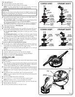
For units with arbors: Install the spacer onto the upper housing. Slide the spacer and upper housing onto the arbor. NOTE: The arbor will perforate the label on the bottom of the lower housing. This will allow the arbor to insert through the unit. NOTICE: Make sure the arbor is fully seated into the hex-shaped pocket on the spacer before proceeding. An arbor that is not fully seated will cause damage to the upper housing and spacer. Secure the trimmer head in place by installing a bolt (M8) through the washer and into the opening in the arbor. For curved shaft models, install the black bolt and turn clockwise. Make sure bolt is fully screwed into arbor. Do not overtighten. For straight shaft models, install the silver bolt and turn counterclockwise. Make sure bolt is fully screwed into arbor. Do not overtighten. Install line as described in Installing Line. For units without arbors: Insert nut (M8), with flange facing down, into the hex pocket in the upper housing then twist upper housing onto the attachment (see figure 6). For curved shaft models, insert silver nut and turn upper housing clockwise. For straight shaft models, insert black nut and turn upper housing counterclockwise. If necessary, use a wrench (not provided) or locking pin to hold the flange washer while tightening the upper housing. Slide lower housing onto the upper housing. Push together until the arrows in the upper housing align to the posts in the lower housing. Push and turn clockwise to the locked position. To replace blades in the fixed line/blade housing: Remove the fixed line/blade housing by rotating the lower housing counterclockwise so the posts and the arrows on the upper housing align, then pull the lower housing away from the upper housing. NOTE: Remove the bolt before rotating housings apart on units that have an arbor. Remove the used blades and discard. Install the new blades, making sure they are fully seated. Reinstall the fixed line/blade housing as previously described. Install line as described in Installing Line. INSTALLING LINE See Figure 8. NOTE: Do not attempt to install line and blades in the fixed line/blade housing at the same time. Stop the engine or motor, disconnect the spark plug wire for gas power heads, remove the battery pack for cordless power heads, or disconnect the plug from the power source for electric power heads. Remove the blades by rotating the lower housing counterclockwise so the arrow on the upper housing aligns with the posts on the lower housing. NOTE: Remove the bolt before rotating housings apart on units that have an arbor. Separate the lower housing from upper housing and set aside. NOTE: It is not necessary to remove the upper string head housing from the drive shaft. Remove the blades and store for future use. Fold a piece of 11 in. line in half so each half is equal in length. NOTE: Some precut .095 in. lines are included with this kit. Insert the ends of the line through the eyelets in the post and pull tight. Repeat with the other post. The fixed line/blade housing is now ready to use. CURVED SHAFT STRAIGHT SHAFT ARBOR SPACER UPPER HOUSING LOWER HOUSING WASHER BLACK BOLT CURVED SHAFT ARBOR SPACER UPPER HOUSING LOWER HOUSING WASHER SILVER BOLT Fig. 5 STRAIGHT SHAFT UPPER LOCKING HOUSING PIN SILVER NUT LOWER HOUSING UPPER HOUSING BLACK NUT LOWER HOUSING Fig. 6 POST EYELET Fig. 7 LINE Fig. 8
-
 1
1 -
 2
2 -
 3
3 -
 4
4 -
 5
5 -
 6
6
 |
 |
