Rane MA 4 MA 4 Amplifier Data Sheet - Page 6
Architectural Specifications
 |
View all Rane MA 4 manuals
Add to My Manuals
Save this manual to your list of manuals |
Page 6 highlights
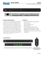
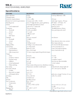
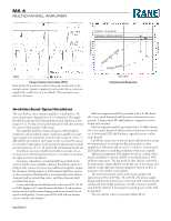
MA 4 MULTICHANNEL AMPLIFIER Attack: 1.5 seconds Release: 3 dB per second Output Power Output dB Power-Factor-Correction (PFC) Near perfect Power-Factor with ⅓ the peak current and ½ the average current (green) compared to non power-factor-corrected supply with conduction of 3 ms (black). The response is measured at 100 watts. OutpOutudtBprue t10P0oWwer Input dBu Compressor Response Architectural Specifications The unit shall be a four channel amplifier. It shall deliver 100 watts of power per channel into a 4 to 8 ohm load. The amplifier shall incorporate load sensing with normal operation in the range of 2 to 16 ohms. Front panel indicators shall alert presence of a channel load outside of this range. The amplifier shall have balanced inputs with Euroblock connectors and Euroblock output connectors capable of accepting 12 gauge wire. Sensitivity controls with a range of +22 to +4 dBu shall be provided for each input on the rear panel by means of screwdriver adjustment. Load sensitive headroom meters shall provide indication of 3, 6, 12 and 24 dB of remaining headroom. Euroblock connectors shall be provided as a means of connecting remote DC level potentiometers or switches to attenuate the input level of each channel. Automatic redundancy switching shall be provided in the event of a fault of any amplifier channel. Euroblock connectors shall provide a means of connecting additional amplifier outputs for automatic backup purposes. Each channel shall have master or slave operation determined by a rear panel dipswitch. Master channels shall write fault flag status, and Slave channels shall read fault flag status. A rear panel dipswitch shall provide a selection of 20, 40, 60 or 80 Hz highpass 2nd-order Butterworth filters. Load sensitive limiter circuits shall prevent clipping and the associated loss of speech intelligibility. A front panel LED shall indicate limiter activity within each channel. Built-in compressors shall be provided with a 10 dB threshold. A rear panel dipswitch shall activate or deactive the compressors. A front panel LED shall indicate compressor activity within each channel. Built-in expanders shall be provided with a -70 dBFS threshold. A rear panel dipswitch shall activate or deactive the expanders. A front panel LED shall indicate expander activity within each channel. Euroblock connectors on the rear panel shall provide a means of transmitting or receiving fault flag information to other amplifiers or indicators with an active 5 volt drive. A front panel LED shall indicate a fault flag condition within each channel. Thermal management shall employ forced air cooling, allowing the amplifiers to operate reliable in ventilated racks at 40°C ambient temperature. The fan speed air flow shall be controlled by temperature. Intake shall be on the left side of the chassis and exhaust on the right side, incorporating low velocity air flow to minimize noise within a rack cabinet. The universal internal switch-mode power supply shall operate from 100 to 240 VAC, 50 or 60 Hz. The power supply design shall provide power-factor-correction with very low inrush current and overvoltage protection. An IEC connector and IEC cord shall be utilized. A front panel mounted power switch shall be provided. The unit shall be a Rane Corporation Model MA 4. Data Sheet-6
-
 1
1 -
 2
2 -
 3
3 -
 4
4 -
 5
5 -
 6
6 -
 7
7 -
 8
8
 |
 |
