Pyle SLFTRD213 Instruction Manual - Page 5
While sliding the Handlebar Bracket onto the Right and Left Handlebar
 |
View all Pyle SLFTRD213 manuals
Add to My Manuals
Save this manual to your list of manuals |
Page 5 highlights
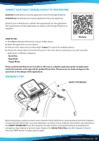
Use two M8x40 Hexagon Socket Oval Head Bolts (S1) and two Spring Washers (S2) to secure both Right and Left Handlebar Support Tubes onto the Base Frame. Use two M8x16 Hexagon Socket Oval Head Bolts (S3) to secure both Right and Left Handlebar Support Tubes onto the Base Frame. Semi-tighten all bolts with the Allen Wrench provided. NOTE: DO NOT FULLY TIGHTEN BOLTS IN STEP 1 UNTIL STEP 2 IS COMPLETED. S3 cable (A) S3 cable (B) S11 S10 S11 S10 STEP 2 It is recommended to have a second person assist with this step. One person should hold the Computer Console in place while the other person connects the cables. Connect the Control Pad signal cable (A) from the right handlebar to the signal cable (B) on right support tube. Install the Handlebar Bracket onto the Right and Left Handlebar Support Tubes, use two Hexagon Socket Oval Head Bolt M8x16 (S3), two Hexagon Socket Oval Head Bolt M8x30 (S10) and two Locknut (S11), lock them by Spanner (S4) and Allen Wrench #5 (S5). IMPORTANT: • While sliding the Handlebar Bracket onto the Right and Left Handlebar • Support Tubes make sure the cables are installed inside the Right Handlebar • Support Tube and pay attention not to pinch the cables. S6 S6 STEP 3 Assemble the left and right end caps (S9) on treadmill frame, tighten by two screws (S6) with cross screwdriver (S5). NOW PLEASE FULLY TIGHTEN ALL BOLTS INSTALLED IN STEP 1 . www.SereneLifeHome.com 5
-
 1
1 -
 2
2 -
 3
3 -
 4
4 -
 5
5 -
 6
6 -
 7
7 -
 8
8 -
 9
9 -
 10
10 -
 11
11 -
12
-
13
-
14
-
15
-
16
 |
 |
