Pyle PSW445T User Guide - Page 2
Hardware List
 |
View all Pyle PSW445T manuals
Add to My Manuals
Save this manual to your list of manuals |
Page 2 highlights
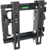
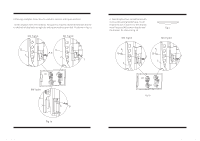
Hardware List: Actual parts appearance and the quantity may different with illustrated. 23 UP UP 1 4 A-F G H I J K ID Qty Description 1 1 Wall mount 2 1 Left bracket 3 1 Right bracket 4 2 Safe bolt A 4 M4×12mm bolt B 4 M4×16mm bolt C 4 M5×16mm bolt D 4 M6×16mm bolt ID Qty Description E 4 M5×36mm bolt F 4 M6×36mm bolt G 4 Square washer H 4 Long bolt I 4 Wall anchor J 4 Long bolt washer K 4 Spacer After determining the height of stand, follow the installation instructions in below to install wall mount to different kinds of wall -wooden, concrete. Wooden wall: Using a awl or nail to make where the nails are located, as shown as fig.2b. Distance between two nails for fixing wall mount must not less than 16". Pre-drill these holes with a 5mm drill bit to at least 40mm in deep hole. Please make sure these holes are level and located at center. Use wall mount as a template to mark the location of other three holes and drill the same holes. Fix the wall mount to the wall with 4 long bolts(H) and washers(J). Concrete wall: Using the wall mount as template to mark 4 holes location on the wall. Please make sure these holes are level and at least 6" between any two lines. Pre-drill these holes with a 10mm drill bit to at least 50mm deep hole. Insert wall anchors(I) into each of these holes. Attach the wall mount to the wall using 4 long bolts(H) and washers(J). 1 Balance-adjusting Fig 2b J H Fig 2c Using balance-adjusting system on the plate, make sure whether wall plate is installed balance. If not, then slide the wall plate let pointer level in the center position.
-
 1
1 -
 2
2 -
 3
3 -
 4
4
 |
 |
