Pyle PMXU68BT Instruction Manual - Page 4
PMX848BT Front and Back Panel, Front and Back Panel Function - mixer
 |
View all Pyle PMXU68BT manuals
Add to My Manuals
Save this manual to your list of manuals |
Page 4 highlights
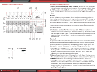
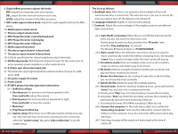
PMX848BT Front and Back Panel 6 www.PyleUSA.com Front and Back Panel Function 1. Mike/Line/Guitar input jacks of MIC channel: The jacks are used to connect microphones or other audio devices in support of cannon plugs and 6.35 plugs. 2. +48V phantom switch/LED: When this switch is turned on, the +48V LED lights and DC +48 V phantom power is supplied to the XLR plug on MIC input jack. NOTICE Be sure to leave this switch o if you do not need phantom power. Follow the important precautions below, in order to prevent noise and possible damage to external devices as well as the mixer if you turn this switch on. Be sure to leave this switch o when you connect a device that does not support phantom power to channel. Make sure to turn this switch o when connecting/disconnecting a cable to/from channel. Slide the knob on channel to minimum before turning this switch ON/OFF. 3. Guitar/Line input shifter: The switch is used to shift the connections to di erent sound sources of the input channels. Switched up, the input channel can be connected directly with a high impedance audio device such an electric guitar or a bass. Switched down, it can be connected to a low-impedance sound device. Warning! In operation of the switch, all level output control (such as channel volume knobs, monitor output knobs and earphone knobs) should be set up to the minimum position. Because this operation will cause a sudden impact sound, which can damage the external devices, and the hearing of the personnel on site. 4. Mic input CH 2 band EQ: This is a high quality, sensitive, 2 segment equalizer that adjusts the overall tone of the channel. The adjustment wave form of the high and low bass equalizer is the shape of the broom, which a ects the frequency of 12KHz and the sound below 80Hz; 5. FX send knob: Adjust the size of the signal sent to the digital e ect processor. The signal transmitting point is located after the volume knob of the channel; 6. PAN knob: Positions the channel signal between L/R in the stereo mix; 7. MIC input volume knob/peak LED: Adjust the volume of the sound input from the microphone or other source connected to channel. When the peak light ashes, indicating that the input signal is too high, please turn the volume knob to the left to reduce the volume. In normal use, please avoid the peak light for a long time; www.PyleUSA.com 7
-
 1
1 -
 2
2 -
 3
3 -
 4
4 -
 5
5 -
 6
6 -
 7
7
 |
 |
