Pyle PB918 Instruction Manual - Page 11
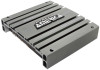
²0. Protection Led, ²1¸ Power Supply, ²2¸ Power Fuse, Speaker Output Terminals
 |
View all Pyle PB918 manuals
Add to My Manuals
Save this manual to your list of manuals |
Page 11 highlights
FUNCTIONS (PB718/PB918/PB2518/PB3818) 10. PROTECTION LED The protection circuitry will disable the amplifier if it senses an input over load, speaker short circuit of extreme high temperature conditions. When the protection circuit is in operation the LED indicator on the unit will light indicating that the amplifier has gone into a self preservation mode. At this time please check your system to see what is causing the protection circuit to fire. The amplifier can be reset by turning the remote power off and then on again. If the system shuts down because of a thermal overload condition, allow the amplifier to cool down, before restarting. If the amplifier shutdown because of an input overload or speaker short circuit please be sure to cor rect these conditions before restarting the amplifier. 11. POWER SUPPLY A. +12V To connect +12V DC power supply wire from the terminal of battery. B. GROUND To connect the ground wire from the chassis of the automobile. C. REMOTE To connect the control wire which provides remote turn on and off of the amplifier by the radio/cassette player.(Usually The Auto Antenna Lead) 12. POWER FUSE The power fuse protects both this amplifier and the automobile electrical system from short circuit conditions. 13. SPEAKER OUTPUT TERMINALS The speaker terminals are for high conductivity and minimum impedance loss. The terminals are facing upwards for easy wiring in tight situations. Be sure to strip just enough insulation off your speaker wires that will fit un der the screw plate to help ensure against speaker wire short circuits. 11
-
 1
1 -
2
-
3
-
4
-
5
-
 6
6 -
 7
7 -
 8
8 -
 9
9 -
 10
10 -
 11
11 -
 12
12 -
 13
13 -
 14
14 -
 15
15 -
 16
16 -
17
 |
 |
