Poulan GTI18KT User Manual - Page 9
handlebar.
 |
View all Poulan GTI18KT manuals
Add to My Manuals
Save this manual to your list of manuals |
Page 9 highlights
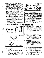
E. BLADE - Model GTI 18KT (not included with Model GTI 18T) A WARNING The metal shield and metal handlebar must be properly installed on the tool anytime the tool is used with the blade. The forward tip on the metal shield helps to reduce the occurrence of blade thrust which can cause serious injury such as amputation to operator or bystanders. A WARNING Failure to install the shield in the position shown in Figures 6 and 9 can result in serious injury to the operator. The length of the shield must be aligned with the length of the tube. NOTE: If your unit is equipped as a line trimmer, remove the plastic shield, grass washer, and trimmer head before installing the metal shield and blade. Be sure to store parts for future use. 1. Position retention plate "P" on the underside of the metal shield and align screw holes. Make sure the flat side of the plate is against shield. 2. Hold retention plate "P" in position and place the metal shield under the bearing housing. Align screw holes. Figure 6 . 3. Insert the four metal shield screws "L."(one at a time) through the bearing housing, shield, and retention plate "P.". Figure 6 . 9. Insert the large hex wrench (provided) into the aligned holes to keep the arbor shaft from turning. Figure 7 . 10.Tighten the hex flange nut firmly with a wrench while holding hex wrench in position. 11.Remove the hex wrench. 12.Turn blade by hand. If blade binds against shield, blade is not centered. Reinstall blade. NOTE: To remove the Blade, insert the large hex wrench into aligned holes. Un-thread the Hex Flange Nut and remove parts. Be sure to store the Retention Plate, hex Flange Nut, Cupped Washer, Flat Washer, 4 Shield Screws, and Metal Shield with the Blade for future use. Bearing Housing Clamp Widest Portion of Shield* Toward Engine v Screw L.* Dust Cup Arbor Shaft Retention A WARNING Parts noted with * are critical and must be supplied by WEED EATER. Failure to use proper parts can cause the blade to fly off and seriously hurt you or others. 4. Tighten the screws evenly and securely with a hex wrench. 5. Remove the packing cover from the arbor shaft if so equipped. 6. Install blade over arbor shaft, making sure the hole in the center of blade is fitted around the raised center step on the dust cup. Figure 6 . 7. Install the large flat washer "M.", cupped washer "N.", and hex flange nut "J." as shown in Figure 6 . Be sure cupped washer "N." is installed as shown in Figure 6 (inset). 8. Align the hole in the dust cup with the hole in the side of the bearing housing by turning the dust cup. Figure 6 . Plate P.* Blade* • Cupped Side Toward Washer N.* Blade Figure 6 Figure 7 Washer M.* Washer N.* (see inset) Nut J.* Hex Wrench F. SHOULDER STRAP CLAMP - Model GTI 18KT (not included with Model GTI 18T) 1. Align shoulder strap clamp between handlebar mounting block and engine. Figure 8 . 2. Firmly push the shoulder strap clamp onto the tube. Figure 8. Be sure that the shoulder strap clamp is installed with the hex shaped recession (on the clamp) facing the same side of the tube as the barrier portion of handlebar. 3. Insert threaded end of screw "K." through the opening in the top of the T- handle. Figure 8 . 4. Pull on the threaded end of screw "K." to bring the square head of the screw past the pin inside the T-handle. 5. Seat nut "I." in the hex-shaped recession on the back side of the shoulder strap clamp. 6. Insert the threaded end of the T- handle screw through the hole in the shoulder strap clamp and tighten firmly by hand only. Engine T--Handle Screw K. Shoulder Strap Clamp Nut I. 16) Handlebar Mounting Block Figure 8 9
-
 1
1 -
2
-
3
-
 4
4 -
 5
5 -
 6
6 -
 7
7 -
 8
8 -
 9
9 -
 10
10 -
 11
11 -
 12
12 -
 13
13 -
 14
14 -
15
-
16
-
17
-
18
-
19
-
20
-
21
-
22
-
23
-
24
-
25
-
26
 |
 |
