Polk Audio 65 65 Mounting Template - Page 1
Polk Audio 65 Manual
 |
View all Polk Audio 65 manuals
Add to My Manuals
Save this manual to your list of manuals |
Page 1 highlights
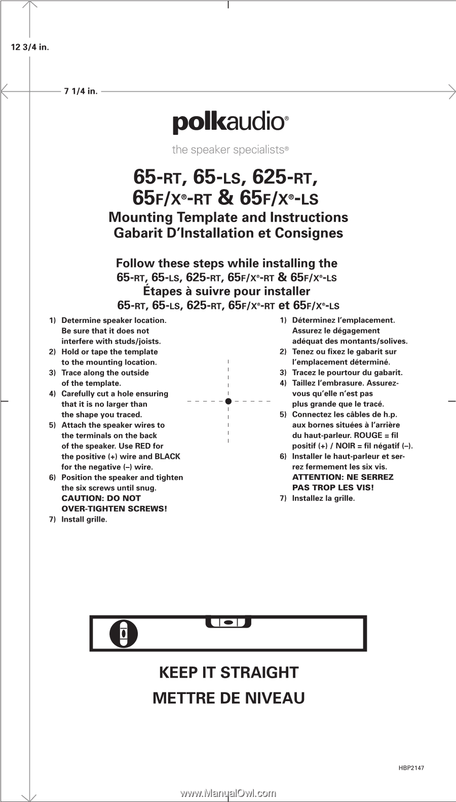
12 3/4 in. 7 1/4 in. polkaudio® the spo...,. „ F,~,~iaiiaLs® 65 - RT, 65-LS, 625-RT, 65F/V-RT & 65F/V-Ls Mounting Template and Instructions Gabarit D'Installation et Consignes Follow these steps while installing the 65-RT, 65-LS, 625-RT, 65F/v-RT & 65F/X®-LS Etapes a suivre pour installer 65-RT, 65-is, 625-RT, 65F/v-RT et 65F/X®-LS 1) Determine speaker location. Be sure that it does not interfere with studs/joists. 2) Hold or tape the template to the mounting location. 3) Trace along the outside of the template. 4) Carefully cut a hole ensuring that it is no larger than • the shape you traced. 5) Attach the speaker wires to the terminals on the back of the speaker. Use RED for the positive (+) wire and BLACK for the negative (-) wire. 6) Position the speaker and tighten the six screws until snug. CAUTION: DO NOT OVER-TIGHTEN SCREWS! 7) Install grille. 1) D6terminez ('emplacement. Assurez le d6gagement adequat des montants/solives. 2) Tenez ou fixez le gabarit sur ('emplacement determine. 3) Tracez le pourtour du gabarit. 4) Taillez ('embrasure. Assurez- vous qu'elle n'est pas plus grande que le trace. 5) Connectez les cables de h.p. aux bornes situ6es a l'arriare du haut-parleur. ROUGE = fil positif (+) / NOIR = fil negatif (-). 6) Installer le haut-parleur et serrez fermement les six vis. ATTENTION: NE SERREZ PAS TROP LES VIS! 7) Installez la grille. 0 KEEP IT STRAIGHT METTRE DE NIVEAU HBP2147
-
 1
1
 |
 |