Pioneer PWM-F110 Owner's Manual - Page 15
Caution, - pwm flat wall mount
 |
UPC - 012563011829
View all Pioneer PWM-F110 manuals
Add to My Manuals
Save this manual to your list of manuals |
Page 15 highlights
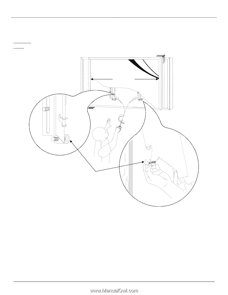
PWM-F110 2. Make any lateral shift adjustments and lock it by tightening the two (2) ¼"-20 Phillips screws found on the bottom of the mounting brackets. Use the wall bumper to adjust your flat panel. CAUTION: Do not over tighten the ¼"-20 screws to the rods (Figure 15). NOTE: To remove the flat panel from the wall, simply back off the ¼"-20 screws using a Phillips screwdriver and lift the unit of the wall carefully. Wall Plate Wall Bumper Figure 15 Installation Manual Page - 15 -
-
 1
1 -
2
-
3
-
4
-
5
-
6
-
7
-
8
-
9
-
 10
10 -
 11
11 -
 12
12 -
 13
13 -
 14
14 -
 15
15 -
 16
16 -
 17
17 -
 18
18
 |
 |
PWM-F110
Installation Manual
Page - 15 -
2.
Make any lateral shift adjustments and lock it by tightening the two (2) ¼”-20 Phillips screws found on
the bottom of the mounting brackets. Use the wall bumper to adjust your flat panel.
CAUTION
:
Do not over tighten the ¼”-20 screws to the rods (Figure 15).
NOTE
:
To remove the flat panel from the wall, simply back off the ¼”-20 screws using a Phillips
screwdriver and lift the unit of the wall carefully.
Figure 15
Wall Plate
Wall
Bumper