Pioneer 434CMX Service Manual - Page 77
COMMON ADJ. mode, INDIVIDUAL ADJ. mode, Function/Display, Remarks, Content
 |
UPC - 012562691107
View all Pioneer 434CMX manuals
Add to My Manuals
Save this manual to your list of manuals |
Page 77 highlights
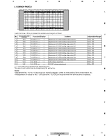
5 6 7 8 INDIVIDUAL ADJ. mode 1 2 3 4 5 6 7 8 9 10 11 12 13 14 15 16 17 18 19 20 21 22 23 24 25 26 27 28 29 30 31 32 33 34 35 36 37 38 39 40 A 1 2 I ND I V I DUAL AD J . I N 1 - 0 1 3 - NT V - 4MX 3 4 5 6 7 8 9 10 11 12 13 14 15 CVY GA I N< = > : 128 16 Each time the 5 or ∞ key is pressed, the individual adjustment items are changed, as follows: B No. Corresponding 232C Command Function/Display Content Adjustable Range Remarks 1 VSG 2 VSO CVY GAIN IC6255 Input GAIN adj. CVY OFFSET IC6255 Input OFFSET adj. 064 to 191 Select a route with the command SWM (main) and the command 064 to 191 SWS (sub). 3 RYG 4 GYG 5 BYG RY GAIN GY GAIN BY GAIN : ∗∗∗ AD (IC6001 or IC6602) R input GAIN adj AD (IC6001 or IC6602) G input GAIN adj AD (IC6001 or IC6602) B input GAIN adj. 000 to 255 000 to 255 000 to 255 The memory tables for the RGB and component systems are separate, and are switchable with the command MCD. "∗∗∗" in the table above represents the adjustment value. The value of each subitem can be changed using the 2 or 3 key. C Note: The differences in signals for the main and sublevel screens from the AV/IO Assy are compensated, and the compensation data are stored in the EEPROM (IC8705) for each screen. COMMON ADJ. mode 1 2 3 4 5 6 7 8 9 10 11 12 13 14 15 16 17 18 19 20 21 22 23 24 25 26 27 28 29 30 31 32 33 34 35 36 37 38 39 40 1 2 COMMON A D J . I N 1 -G3 2 - RGB - 4MX 3 4 D 5 6 7 8 9 10 11 12 13 14 15 RGB 1 16 Each time the 5 or ∞ key is pressed, the subitems are changed, as follows: • RGB1(+) : Adjustment of a video card and the RGB Assy • RGB2(+) : Adjustment of the RGB Assy • PANEL1(+) : Adjustment items related to the drive (common to the unit) E • PANEL2(+) : Adjustment items related to the drive (dependent on signals) Each time the SET key is pressed, items grouped under the subitem are selected one by one. F PDP-434CMX 77 5 6 7 8
-
 1
1 -
2
-
3
-
4
-
5
-
6
-
7
-
8
-
9
-
10
-
11
-
12
-
13
-
14
-
15
-
16
-
17
-
18
-
19
-
20
-
21
-
22
-
23
-
24
-
25
-
26
-
27
-
28
-
29
-
30
-
31
-
32
-
33
-
34
-
35
-
36
-
37
-
38
-
39
-
40
-
41
-
42
-
43
-
44
-
45
-
46
-
47
-
48
-
49
-
50
-
51
-
52
-
53
-
54
-
55
-
56
-
57
-
58
-
59
-
60
-
61
-
62
-
63
-
64
-
65
-
66
-
67
-
68
-
69
-
70
-
71
-
 72
72 -
 73
73 -
 74
74 -
 75
75 -
 76
76 -
 77
77 -
 78
78 -
 79
79 -
 80
80 -
 81
81 -
 82
82 -
83
-
84
-
85
-
86
-
87
-
88
-
89
-
90
-
91
-
92
-
93
-
94
-
95
-
96
-
97
-
98
-
99
-
100
-
101
-
102
-
103
-
104
-
105
-
106
-
107
-
108
-
109
-
110
-
111
-
112
-
113
-
114
-
115
-
116
-
117
-
118
-
119
-
120
-
121
-
122
-
123
-
124
-
125
-
126
-
127
-
128
-
129
-
130
-
131
-
132
-
133
-
134
-
135
-
136
-
137
-
138
-
139
-
140
-
141
-
142
-
143
-
144
-
145
-
146
-
147
-
148
-
149
-
150
-
151
-
152
-
153
 |
 |
