NEC NP-P525WL User Manual English - Page 119
Design and manufacturing conditions for the stand
 |
View all NEC NP-P525WL manuals
Add to My Manuals
Save this manual to your list of manuals |
Page 119 highlights
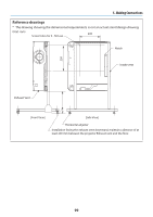
5. Making Connections Design and manufacturing conditions for the stand Please engage an installation service provider for the design and manufacture of the customized stand to be used for portrait projection. Please ensure that the following are complied with when designing the stand. 1. Installation facing the exhaust vent downward, maintain a distance of at least 200 mm between the projector exhaust vent and the floor. Do not obstruct the intake vent at the rear of the projector. 2. Use the four screw holes on the bottom face of the projector to secure it to the stand. Screw hole center dimension: 200 × 250 mm Screw hole dimension on the projector: M4 with a maximum depth of 8 mm. * Please design the stand such that the rear legs on the bottom face of the projector do not contact the stand. The tilt foot can be turned and removed. 3. Horizontal adjustment mechanism (for example, bolts and nuts in four locations) 4. Please design the stand such that it does not topple over easily. 98
-
 1
1 -
2
-
3
-
4
-
5
-
6
-
7
-
8
-
9
-
10
-
11
-
12
-
13
-
14
-
15
-
16
-
17
-
18
-
19
-
20
-
21
-
22
-
23
-
24
-
25
-
26
-
27
-
28
-
29
-
30
-
31
-
32
-
33
-
34
-
35
-
36
-
37
-
38
-
39
-
40
-
41
-
42
-
43
-
44
-
45
-
46
-
47
-
48
-
49
-
50
-
51
-
52
-
53
-
54
-
55
-
56
-
57
-
58
-
59
-
60
-
61
-
62
-
63
-
64
-
65
-
66
-
67
-
68
-
69
-
70
-
71
-
72
-
73
-
74
-
75
-
76
-
77
-
78
-
79
-
80
-
81
-
82
-
83
-
84
-
85
-
86
-
87
-
88
-
89
-
90
-
91
-
92
-
93
-
94
-
95
-
96
-
97
-
98
-
99
-
100
-
101
-
102
-
103
-
104
-
105
-
106
-
107
-
108
-
109
-
110
-
111
-
112
-
113
-
 114
114 -
 115
115 -
 116
116 -
 117
117 -
 118
118 -
 119
119 -
 120
120 -
 121
121 -
 122
122 -
 123
123 -
 124
124 -
125
-
126
-
127
-
128
-
129
-
130
-
131
-
132
-
133
-
134
-
135
-
136
-
137
-
138
-
139
-
140
-
141
-
142
-
143
-
144
-
145
-
146
-
147
-
148
-
149
-
150
-
151
-
152
-
153
-
154
-
155
-
156
-
157
-
158
-
159
-
160
-
161
-
162
-
163
-
164
-
165
-
166
-
167
-
168
-
169
-
170
-
171
-
172
-
173
-
174
-
175
 |
 |
