Metabo WEP 17-150 Quick Operating Instructions 2 - Page 12
Switching On and Off
 |
View all Metabo WEP 17-150 Quick manuals
Add to My Manuals
Save this manual to your list of manuals |
Page 12 highlights
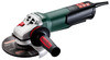
en ENGLISH - Position the "Quick" clamping nut on the spindle so that the 2 lugs engage in the 2 grooves on the spindle. (1) (3) See illustration on page 2. - Tighten the "Quick"clamping nut by turning clockwise by hand. - Turn the grinding wheel firmly clockwise to tighten the "Quick"clamping nut. Releasing the clamping nut (1): Only when the "Quick" clamping nut (1) is attached must the spindle be stopped using the red M-Quick spindle locking button! (4) - The machine continues to run after switching off. - Press in the M-Quick spindle locking button just before the grinding disc stops. (4) The "Quick" clamping nut (1)loosens itself by around half a turn and can be removed without additional effort or tools. 0 I Avoid inadvertent starts: always switch the tool off when the plug is removed from the mains socket or if there has been a power cut. In continuous operation, the machine continues running if it is forced out of your hands. Therefore, always hold the machine with both hands using the handles provided, stand securely and concentrate. Avoid the machine swirling up or taking in dust and chips. After switching off the machine, only place it down when the motor has come to a standstill. Machines with slide switch: 5 6.4 Securing/Releasing the 2-hole nut (depending on features) Securing the 2-hole nut (13): The 2 sides of the 2-hole nut are different. Screw the 2-hole nut onto the spindle as follows: See illustration B on page 2. - X) For thin grinding discs: The edge of the 2-hole nut (13) faces upwards so that the thin grinding disc can be attached securely. Y) For thick grinding discs: The edge of the 2-hole nut (13) faces downwards so that the 2-hole nut can be attached securely to the spindle. - Locking the spindle. Turn the 2-hole nut (13)clockwise using the 2-hole spanner (14) to secure. Releasing the 2-hole nut: - Lock the spindle (see chapter 6.1). Turn the 2-hole nut (13) anticlockwise using the 2-hole spanner (14) to unscrew. 7. Use 7.1 Adjusting the speed (depending on features) Set the recommended speed at the thumbwheel. (8) (small number = low speed; large number = high speed) Cutting disc, roughing disc, cup wheel and diamond cutting disc: high speed Brush: medium speed Sanding plate: low to medium speed Note: We recommend using our angle polisher for polishing work. 7.2 Switching On and Off Always guide the machine with both hands. Switch on first, then guide the accessory towards the workpiece. 12 Switching on: Push the sliding switch forward. (5) For continuous activation, now tilt downwards until it engages. Switching off: Press the rear end of the slide switch (5) and release it. Machines with paddle switch (with dead man function): 89 0 I Switching on: Slide the switch-on lock (10) in the direction of the arrow and press the trigger (9). Switching off: Release the trigger switch. (9) 7.3 Working Directions Grinding and sanding operations: Press down the machine evenly on the surface and move back and forth so that the surface of the workpiece does not become too hot. Rough grinding: position the machine at an angle of 30° - 40° for the best working results. Abrasive cutting-off operations: Always work against the run of the disc (see illustration). Otherwise there is the danger of the machine kicking back from the cut out of control. Guide the machine evenly at a speed suitable for the material being processed. Do not tilt, apply excessive force or sway from side to side. Wire brushing: Press down the machine evenly. 7.4 Rotate gear housing See illustration D on page 3. - Disconnect from the power supply. - Unscrew the fastening screw (a) of the lever (15). Remove the screw, lever (with its sheet metal part) and put aside. - Unscrew the 4 gear housing screws (b). CAUTION! Do not remove the gear housing!
-
 1
1 -
2
-
3
-
4
-
5
-
6
-
 7
7 -
 8
8 -
 9
9 -
 10
10 -
 11
11 -
 12
12 -
 13
13 -
 14
14 -
 15
15 -
 16
16 -
 17
17 -
18
-
19
-
20
-
21
-
22
-
23
-
24
-
25
-
26
-
27
-
28
-
29
-
30
-
31
-
32
 |
 |
