Maytag WVW57UC6FS Installation Guide - Page 12
SEL0113400
 |
View all Maytag WVW57UC6FS manuals
Add to My Manuals
Save this manual to your list of manuals |
Page 12 highlights
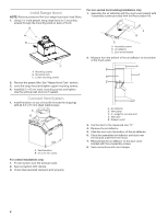
BK WH YL/GN YL/GN BK BU WH BR YL LN Gnd EMI Filter WIRING DIAGRAM Mechanical Push Buttons (4 buttons 3 speeds) Push Button Switch Operation FUNCTION POSITION Off No Connection Lamps Brown/Yellow (L-1) Low Speed Brown/White (L-2) Med Speed Brown/Blue (L-3) WH High Speed Brown/Black (L-4) WH BU BK YL WH BR WH RD BK YL BU BU BK GY YL/GN BU YL BK LED Driver + Output: 700mA (2-15 VDC) - Input: 120 VAC BK BU RD SEL0113400 BU GY BK RD WH YL BR YL/GN Motor Specifications Power Supply Frequency 120 VAC 60 Hz Power Absorption 240 W Motor Resistance (Ω) Blue/Black 17.7 Blue/Gray 27.1 Blue/Red 34.6 Blue/White 41.2 12
-
 1
1 -
2
-
3
-
4
-
5
-
6
-
 7
7 -
 8
8 -
 9
9 -
 10
10 -
 11
11 -
 12
12 -
 13
13 -
 14
14 -
 15
15 -
 16
16 -
 17
17 -
18
-
19
-
20
-
21
-
22
-
23
-
24
-
25
-
26
-
27
-
28
 |
 |

12
WIRING DIAGRAM
L
N
Gnd
WH
Mechanical Push Buttons
(4 buttons 3 speeds)
SEL0113400
Motor Specifications
Power Supply
Frequency
Power Absorption
240 W
120 VAC
60 Hz
Blue/Black
Blue/Gray
Blue/Red
Blue/White
17.7
27.1
34.6
41.2
Push Button
Switch Operation
POSITION
FUNCTION
Off
Lamps
Low Speed
Med Speed
High Speed
No Connection
YL/GN
WH
BK
YL/GN
WH
WH
WH
WH
BK
BK
BK
BK
BU
BU
BU
BU
BU
BU
BR
BR
BR
YL
YL
YL
YL
RD
RD
RD
BK
BK
BU
EMI Filter
LED
Driver
Brown/Black (L-4)
Brown/Yellow (L-1)
Brown/White (L-2)
Brown/Blue (L-3)
YL
Output: 700mA (2-15 VDC)
Input: 120 VAC
Motor Resistance
(Ω)
+
-
YL/GN
YL/GN
WH
BK
GY
GY