LiftMaster RSW12U RSW12U Installation Manual
LiftMaster RSW12U Manual
 |
View all LiftMaster RSW12U manuals
Add to My Manuals
Save this manual to your list of manuals |
LiftMaster RSW12U manual content summary:
- LiftMaster RSW12U | RSW12U Installation Manual - Page 1
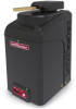
Model RSW12U RESIDENTIAL DC VEHICULAR SWING GATE OPERATOR INSTALLATION MANUAL • THIS PRODUCT IS TO BE INSTALLED AND SERVICED BY A TRAINED GATE SYSTEMS TECHNICIAN ONLY. • This model is for use on vehicular passage gates ONLY and not intended for use on pedestrian passage gates. • This model is - LiftMaster RSW12U | RSW12U Installation Manual - Page 2
- LiftMaster RSW12U | RSW12U Installation Manual - Page 3
29 TROUBLESHOOTING 30 DIAGNOSTIC CODES 30 CONTROL BOARD LEDS 33 TROUBLESHOOTING CHART 34 APPENDIX 36 DUAL GATE SETTINGS must read and fully understand this manual and follow all safety instructions. • DO NOT attempt repair or service of your gate operator unless you are an Authorized - LiftMaster RSW12U | RSW12U Installation Manual - Page 4
a single device to cover both the opening and closing directions is in accordance with FOLLOW ALL INSTRUCTIONS. • NEVER let children operate or play with gate controls. gate is not moving. • KEEP GATES PROPERLY MAINTAINED. Read the owner's manual. Have a qualified service person make repairs to gate - LiftMaster RSW12U | RSW12U Installation Manual - Page 5
• Photoelectric Sensors • Screen Mesh • Vertical Posts • Instructional and Precautionary Signage 4. Install the gate operator only when: a. The operator is appropriate for the construction and the usage class of the gate. b. All openings of a horizontal slide gate are guarded or screened from the - LiftMaster RSW12U | RSW12U Installation Manual - Page 6
in the horizontal plane parallel to the roadway, between a fixed stationary object nearest the roadway, (such as a gate support post) and the gate frame when the gate is in either the fully open position or the fully closed position, shall not exceed 2 1/4 inches (57 mm), refer to ASTM F2200 for - LiftMaster RSW12U | RSW12U Installation Manual - Page 7
INTRODUCTION CARTON INVENTORY NOT SHOWN: Documentation packet and hardware bag Operator Arm Assembly Cover Warning Signs (2) and Warranty Card Battery 12 Vdc 7AH Key (2) LiftMaster Monitored Retro-Reflective Photoelectric Sensor 5 - LiftMaster RSW12U | RSW12U Installation Manual - Page 8
applications: Usage Classification Main AC Supply System Operating Voltage Accessory Power Solar Power Max Maximum Gate Weight/Length 90 Degree Travel Time* Maximum Travel Range* Maximum Daily Cycle Rate Maximum Duty Cycle Operating Temperature Expansion Board Inherent Entrapment Protection (Type - LiftMaster RSW12U | RSW12U Installation Manual - Page 9
vehicle loops allow the gate to stay open when vehicles are obstructing the gate path. Suggested for vehicles 14 feet (4.27 m) or longer. Vehicle loops are not required but are recommended. Entrapment Danger CHECK YOUR GATE Gate MUST be level. Gate and gate post MUST be plumb. Gate MUST have smooth - LiftMaster RSW12U | RSW12U Installation Manual - Page 10
to the Appendix in the back of the manual for more information). SINGLE GATE Photoelectric Sensors Warning Sign Operator Edge Sensors NOTE the opening or closing direction. Care shall be exercised to reduce the risk of nuisance tripping, such as when a vehicle, trips the sensor while the gate is - LiftMaster RSW12U | RSW12U Installation Manual - Page 11
AND OPERATOR For compact installation refer to the Appendix for installation steps 1-4, pages 38-39. DO NOT run the operator until instructed. The illustration below shows the recommended dimensions for a standard installation. If these dimensions are not applicable for your installation refer to - LiftMaster RSW12U | RSW12U Installation Manual - Page 12
dimension D. Example: D = 42", if the dimensions between the gate and the concrete pad is 32". DISTANCE If this dimension is between 20 and 32 inches, a compact installation is necessary. Refer to Appendix for compact installation instructions. CHART A ABCDE CHART B ABCDE 1 46" 35.5" 29.5" 35 - LiftMaster RSW12U | RSW12U Installation Manual - Page 13
INSTALLATION STEP 2 CONCRETE PAD AND OPERATOR ATTACHMENT 5.5" CONDUIT LOCATION 1" 4.5" CHECK the national and local building codes before installation. NOTE: When lifting the operator use the handle to avoid damaging the operator. 1. Install the electrical conduit. 4" 6.5" 1.5" 2. Pour a - LiftMaster RSW12U | RSW12U Installation Manual - Page 14
not allow arms to scissor when open). Measure both sections of the arm (D and C). The arm lengths are correct as long as C+D=E (arm should be perpendicular to the gate in the open position as shown). TOP VIEW - CLOSED GATE Set Screws 1 E TOP VIEW - OPEN GATE Gate Open 90° Output Shaft 2 Set - LiftMaster RSW12U | RSW12U Installation Manual - Page 15
INSTALLATION STEP 5 SECURE THE OPERATOR ARM Once the operator arm measurements are verified: 1. Weld the gate bracket to the gate. 2. Weld the short arm section. 3. Weld the long arm section. 4. Remove the set screws from the arm. NOTE: Completely weld around the outer tubing and - LiftMaster RSW12U | RSW12U Installation Manual - Page 16
obligated to test entrapment protection devices monthly. Use only LiftMaster approved entrapment protection devices (refer to the accessory page). blocked, then ALL gate operation in that direction will stop. Entrapment protection is required for the area between the open gate and the operator. - LiftMaster RSW12U | RSW12U Installation Manual - Page 17
specific entrapment protection device manual for more information. These gate closing the gate will reverse to the full open position, disengaging the Timer-to-Close. This input will be disregarded during gate opening. Open Photoelectric Sensors OR Open Edge OPEN EYES/EDGE (2 Terminals) The OPEN - LiftMaster RSW12U | RSW12U Installation Manual - Page 18
and secured, at that time the unit may be returned to service. • Disconnect power at the fuse box BEFORE proceeding. Operator MUST panel (not provided). Follow the directions according to your application. For dual gate applications, power will have to be connected to each operator. Main power - LiftMaster RSW12U | RSW12U Installation Manual - Page 19
. 11. Turn ON AC power to the operator. Junction Box Cover To use a 33AH battery in place of the 7AH battery, follow the instructions below. The 33AH application requires the 33AH wire harness (Model K94-37236). 33AH BATTERY 1. Unplug the transformer. 2. Unplug the J15 plug labeled BATT - LiftMaster RSW12U | RSW12U Installation Manual - Page 20
. Wired dual gate applications will have a longer battery standby time than wireless applications. WIRED DUAL GATES TO ACTIVATE THE the primary operator. The yellow NETWORK LED will light. 4. Press and release the OPEN test button to assign this operator as network primary. 5. Press and release the - LiftMaster RSW12U | RSW12U Installation Manual - Page 21
to close before the other. The operator with the LOCK/BIPART DELAY switch ON will delay from the close limit when opening and be the first to close from the open limit. SLIDE GATE APPLICATIONS: Not applicable, set to OFF. • SYNCHRONIZED CLOSE The BIPART DELAY is also used in applications where one - LiftMaster RSW12U | RSW12U Installation Manual - Page 22
INSTALLATION STEP 10 INSTALL THE COVER The operator cover consists of two pieces: a rear cover and a front cover. The front cover can easily be removed to access the electrical box. To access the reset switch slide the access door up. The front cover and access door can be locked with the key. 1. - LiftMaster RSW12U | RSW12U Installation Manual - Page 23
which limit is being set. 4. Press and hold one of the MOVE GATE button to move the gate to the other limit. 5. Press and release the SET CLOSE or SET OPEN button depending on which limit is being set. 6. Cycle the gate open and close. This automatically sets the force. When limits are set properly - LiftMaster RSW12U | RSW12U Installation Manual - Page 24
injury to a person. The force setting is the same for both the open and close gate directions. 1. Open and close the gate with the test buttons. 2. If the gate stops or reverses before reaching the fully open or closed position, increase the force by turning the force control slightly clockwise - LiftMaster RSW12U | RSW12U Installation Manual - Page 25
Program a single button on the remote control for open only. The Timer-to-Close can be set to close the gate. 1. Press and release the LEARN button (operator and, if not installed and used in accordance with the instructions, may cause harmful interference to radio communications. However, there - LiftMaster RSW12U | RSW12U Installation Manual - Page 26
the operator will beep if programming is successful. The status as shown by the LiftMaster Internet Gateway app will be either "open" or "closed". The gate operator can then be controlled through the LiftMaster Internet Gateway app. ERASE ALL CODES 1. Press and release the LEARN button (operator - LiftMaster RSW12U | RSW12U Installation Manual - Page 27
. See Force Adjustment section. 9 TEST BUTTONS: The TEST BUTTONS will operate the gate (OPEN, STOP and CLOSE). 10 STATUS LEDs: The STATUS LEDs indicate the status of the operator. See Status LED Chart in the Troubleshooting section. 11 DIAGNOSTICS Display: The diagnostics code display will show the - LiftMaster RSW12U | RSW12U Installation Manual - Page 28
Release the handle on the operator arm to allow the gate to be opened and closed manually. On a dual gate application the handle must be released on both operators. To resume normal function tighten the handle by pushing it down. Manual Disconnect Handle RESET SWITCH The reset switch is located on - LiftMaster RSW12U | RSW12U Installation Manual - Page 29
exit probe, telephone entry, external exit loop detector, or any device that would command the gate to open. • Opens a closing gate and holds open an open gate, if maintained, pauses Timer-to-Close at OPEN limit. SHADOW (2 Terminals) This input is used for external shadow loop detector when loop is - LiftMaster RSW12U | RSW12U Installation Manual - Page 30
safeties and resets alarm condition). If maintained, pauses Timer-to-Close at OPEN limit. Opens a closing gate and holds open an open gate (within line-of-sight). • CLOSE and COM: Closes an open gate. Hard close (maintained switch overrides external safeties and resets alarm condition within - LiftMaster RSW12U | RSW12U Installation Manual - Page 31
AND FOLLOW ALL INSTRUCTIONS. • ANY manual disconnect release ONLY when the gate is NOT moving. • KEEP GATES PROPERLY MAINTAINED. Read the owner's manual. Have a qualified service person make repairs to gate hardware. • ALL maintenance MUST be performed by a LiftMaster professional. • Activate gate - LiftMaster RSW12U | RSW12U Installation Manual - Page 32
TROUBLESHOOTING To protect against fire and electrocution: • DISCONNECT power (AC or solar and battery) BEFORE installing or servicing operator. For continued out after two minutes of inactivity. Press the OPEN button Ptroescsycthlee tOoPtEhNe mbuotstot n toreccyecnlet ctodthee("m01o"s).t - LiftMaster RSW12U | RSW12U Installation Manual - Page 33
- LiftMaster Plug-in Loop Detector only) Check loop wiring throughout connection. May be a short in the loop, or an open connection in the loop. Wireless edge battery low Replace batteries in wireless edge. Run-Distance Error Gate unbalance detected. Make sure the gate is installed on a level - LiftMaster RSW12U | RSW12U Installation Manual - Page 34
TROUBLESHOOTING DIAGNOSTIC CODES continued... Some codes are saved in the code history and some are not. If a code is not saved it will briefly appear on the display as it occurs, then disappear. LiftMaster installed. Review monitored entrapment 3 minutes obstruction. OPEN EYE/EDGE held more - LiftMaster RSW12U | RSW12U Installation Manual - Page 35
TROUBLESHOOTING CONTROL BOARD LEDS STATUS LEDS INPUT OFF POWER ON OFF state is paused per second) FASTEST BLINK (8 The timer is canceled blinks per second) GATE OFF MOVING ON The gate is stopped The gate is opening or closing MEDIUM BLINK (1 Operator is in E1 (single blink per second) - LiftMaster RSW12U | RSW12U Installation Manual - Page 36
limit. Repair gate as needed. Gate does not fully open or fully close when setting limits. a) Gate does not move to a limit position b) Gate is too difficult to move a) Use manual disconnect, manually move gate, and ensure gate moves easily limit to limit. Repair gate as needed. b) Gate must move - LiftMaster RSW12U | RSW12U Installation Manual - Page 37
TROUBLESHOOTING TROUBLESHOOTING CHART continued... SYMPTOM POSSIBLE CAUSES Obstruction in a) Force adjustment needed gate's path does not cause gate to stop and reverse Photoelectric sensor does not stop or reverse gate batteries On dual-gate system, incorrect gate opens first or closes - LiftMaster RSW12U | RSW12U Installation Manual - Page 38
TROUBLESHOOTING TROUBLESHOOTING CHART continued... open first & close last) Tandem Mode: OFF Synchronized Close: ON ACCESSORY PRIMARY OPERATOR Remote Controls Program remote controls 1 to 50 to the primary operator. LiftMaster Program to primary Internet Gateway operator. Garage and Gate - LiftMaster RSW12U | RSW12U Installation Manual - Page 39
COMPACT INSTALLATION The illustration is an example of a compact installation. If the operator arm will hit an obstruction when the gate is in the open position follow the directions for Compact Installation. (Inside Property) UPHILL DRIVEWAY INSTALLATION The illustration is an example of an uphill - LiftMaster RSW12U | RSW12U Installation Manual - Page 40
OPERATOR COMPACT INSTALLATION ONLY DO NOT run the operator until instructed. Refer to the illustration to determine the measurements and location greater than 4" (10.2 cm) entrapment protection for this area is required. Gate Open 90° Output Shaft Center 26-1/2" 9" 28" Handle STEP 2 CONCRETE PAD - LiftMaster RSW12U | RSW12U Installation Manual - Page 41
arm onto the output shaft so that the pin slides into the slot. 2. Measure 33 inches along the gate length from the gate hinge center. 3. Measure 27.5 inches up from the concrete pad to the gate hinge position on the gate as shown. 4. Make sure the operator arm is level and tack weld the - LiftMaster RSW12U | RSW12U Installation Manual - Page 42
board if it is not in use to improve performance. We recommend LiftMaster low power draw accessories to minimize power draw, refer to accessory be located in an open area clear of obstructions and shading for the entire day. The gate operator is not supported in northern climates where temperatures - LiftMaster RSW12U | RSW12U Installation Manual - Page 43
STEP 8 continued... SOLAR PANEL(S) SOLAR USAGE GUIDE Typical System Standby Battery Current Consumption (mA) System voltage Main board with no radios programmed One or more LiftMaster® remote controls programmed MyQ® device or wireless dual gate programmed Expansion board Per loop detector LOOPDETLM - LiftMaster RSW12U | RSW12U Installation Manual - Page 44
APPENDIX STEP 8 continued... SOLAR PANEL(S) The location of the panel(s) is critical to the success of the installation. In general, the panel(s) should be mounted using the provided angle bracket facing due south. Use a compass to determine direction. The solar panel(s) should be mounted in an - LiftMaster RSW12U | RSW12U Installation Manual - Page 45
Red Wire (+) If necessary, connect additional 12V solar panels in parallel to achieve the desired wattage (30W maximum). Proceed to the Dual Gate section (if applicable) or proceed to the Adjustment section. 10W solar panel installation 20W solar panel installation 30W solar panel installation 43 - LiftMaster RSW12U | RSW12U Installation Manual - Page 46
button on the remote control. 7. Press and release the CLOSE button on the remote control again to set the close limit. 8. Cycle the gate open and close. This automatically sets the force. When limits are set properly the operator will automatically exit limit setting mode. ADJUST THE LIMITS If - LiftMaster RSW12U | RSW12U Installation Manual - Page 47
or solar and battery) BEFORE installing or servicing operator. For continued protection against fire: • Cable Primary/Secondary link to other gate operator Ground the shield of the EXEIXTIT Wire Loop Wire Loop Wire Loop Field Wiring 45 OPEN CLOSE 1 EYE ONLY 2 EYE/ EDGE 3 EYE/ - LiftMaster RSW12U | RSW12U Installation Manual - Page 48
Release Handle Q060 Output Shaft with sprocket, #35 limit chain, and APS sprocket roll pin K77-36539 REPAIR PARTS Cludge Cover K13-36117-1 Cludge Assembly Q061 Output Arm Q059 NOT SHOWN K94-37336 K94-37230 Q103 K94-37236 Wiring Harness with product ID assembly Battery Harness (for 7AH batteries) - LiftMaster RSW12U | RSW12U Installation Manual - Page 49
MONITORED EDGE (6 FT)** Model WR6 REMOTE CONTROLS LiftMaster offers a variety of LiftMaster remote controls to satisfy your application needs. Single Model 890MAX SECURITY+ 2.0® LEARNING REMOTE CONTROLS One button can control a gate operator and the other(s) can control garage door(s). It can also - LiftMaster RSW12U | RSW12U Installation Manual - Page 50
LiftMaster low power accessory. Model LD7LP VEHICLE SENSING PROBE The vehicle sensing probe is buried in the ground and can detect a car as it approaches and will then open the gate MUST be set between 45°F and 60°F to ensure proper gate operation. The heater can be powered by 110 to 250 Vac - LiftMaster RSW12U | RSW12U Installation Manual - Page 51
our service center for warranty repair. You will be advised of shipping instructions when you call. Please include a brief description of the problem and AUTHORIZED TO ASSUME FOR US ANY OTHER LIABILITY IN CONNECTION WITH THE SALE OF THIS PRODUCT. Some states do not allow the exclusion or limitation - LiftMaster RSW12U | RSW12U Installation Manual - Page 52
01-37841C COLOR 845 Larch Avenue Elmhurst, Illinois 60126-1196 LiftMaster.com © 2015, LiftMaster - All Rights Reserved
-
 1
1 -
 2
2 -
 3
3 -
 4
4 -
 5
5 -
 6
6 -
 7
7 -
8
-
9
-
10
-
11
-
12
-
13
-
14
-
15
-
16
-
17
-
18
-
19
-
20
-
21
-
22
-
23
-
24
-
25
-
26
-
27
-
28
-
29
-
30
-
31
-
32
-
33
-
34
-
35
-
36
-
37
-
38
-
39
-
40
-
41
-
42
-
43
-
44
-
45
-
46
-
47
-
48
-
49
-
50
-
51
-
52
 |
 |

RESIDENTIAL DC
VEHICULAR SWING GATE OPERATOR
Model
RSW12U
INSTALLATION MANUAL
LiftMaster
845 Larch Avenue
Elmhurst, IL 60126-1196
•
THIS PRODUCT IS TO BE INSTALLED
AND SERVICED BY A TRAINED GATE
SYSTEMS TECHNICIAN ONLY.
•
This model is for use on vehicular
passage gates ONLY and not intended for
use on pedestrian passage gates.
•
This model is intended for use in Class I
and II vehicular swing gate applications.
•
Visit LiftMaster.com to locate a
professional installing dealer in your area.
•
This gate operator is compatible with
MyQ
®
and Security+ 2.0
®
accessories.