LiftMaster RSL12UL Owners Manual - English French
LiftMaster RSL12UL Manual
 |
View all LiftMaster RSL12UL manuals
Add to My Manuals
Save this manual to your list of manuals |
LiftMaster RSL12UL manual content summary:
- LiftMaster RSL12UL | Owners Manual - English French - Page 1
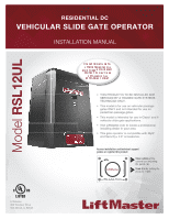
RESIDENTIAL DC VEHICULAR SLIDE GATE OPERATOR INSTALLATION MANUAL Model RSL12UL LiftMaster 300 Windsor Drive Oak Brook, IL 60523 • THIS PRODUCT IS TO BE INSTALLED AND SERVICED BY A TRAINED GATE SYSTEMS TECHNICIAN ONLY. • This model is for use on vehicular passage gates ONLY and not intended for - LiftMaster RSL12UL | Owners Manual - English French - Page 2
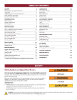
NOTE: • BEFORE attempting to install, operate or maintain the operator, you must read and fully understand this manual and follow all safety instructions. • DO NOT attempt repair or service of your gate operator unless you are an Authorized Service Technician. MECHANICAL ELECTRICAL WARNING: This - LiftMaster RSL12UL | Owners Manual - English French - Page 3
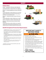
monitored entrapment protection devices in each entrapment zone l This vehicular slide gate operator will operate only after installation of a minimum of two independent* monitored entrapment protection devices in each direction; two in the open direction and two in the close direction. l Entrapment - LiftMaster RSL12UL | Owners Manual - English French - Page 4
l Screen Mesh by a moving gate or barrier. l Vertical Posts l Instructional and Precautionary Signage 4. Install the gate operator only when: a. The operator is appropriate for the construction and the usage class of the gate. b. All openings of a horizontal slide gate are guarded or screened from - LiftMaster RSL12UL | Owners Manual - English French - Page 5
6 feet (1.83 m) above grade. An existing gate latch shall be disabled when a manually operated gate is retrofitted with a powered gate operator. A gate latch shall not be installed on an automatically operated gate. Protrusions shall not be permitted on any gate, refer to ASTM F2200 for Exceptions - LiftMaster RSL12UL | Owners Manual - English French - Page 6
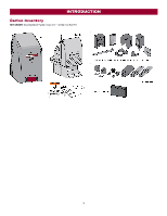
INTRODUCTION Carton Inventory NOT SHOWN: Documentation Packet, Chain #41 - 30 feet, Eye Bolt Kit 6 - LiftMaster RSL12UL | Owners Manual - English French - Page 7
Amps including Accessory Outlets) System Operating Voltage 12 Vdc Battery Run / Battery Backup Accessory Power 12 Vdc, 500mA max. for ON + SW (switched) Solar Power Max 12 Vdc at 30 watts max. Maximum Gate Weight 800 lbs (363.6 kg) Minimum Gate Travel Distance 25 feet (7.62 m) Maximum - LiftMaster RSL12UL | Owners Manual - English French - Page 8
property, where easily visible. Gate Gate must be constructed and installed according to ASTM F2200 standards (refer to page 4). Gate must fit specifications of operator (refer to specifications). Additional Accessories The vehicle loops allow the gate to stay open when vehicles are obstructing - LiftMaster RSL12UL | Owners Manual - English French - Page 9
utility lines, l ALWAYS wear protective gloves and eye protection when changing contact underground utility locating companies BEFORE digging more the battery or working around the battery compartment. than 18 inches (46 cm) deep. Types of Installations Standard Installation Rear Installation 9 - LiftMaster RSL12UL | Owners Manual - English French - Page 10
The gate operator should be installed near the front roller of the gate. Lay out the concrete pad. 2. Install the electrical conduit. 3. Pour a concrete pad (reinforced concrete is recommended). Rear Installation 1. The gate operator should be installed near the back of the gate in the OPEN position - LiftMaster RSL12UL | Owners Manual - English French - Page 11
INSTALLATION Step 2 Install the Operator Attach the operator to the concrete pad with appropriate fasteners. The gate operator should be installed near the front roller of the gate or near the back of the gate (in the OPEN position). The space between the gate and the output sprocket must be a - LiftMaster RSL12UL | Owners Manual - English French - Page 12
3 Attach the Chain Standard Installation DO NOT run the operator until instructed. 1. Manually open the gate and line up the front bracket so the chain will be level with the idler pulley and parallel to the ground. Weld the front bracket in this position. 2. Manually close the gate and line up the - LiftMaster RSL12UL | Owners Manual - English French - Page 13
devices after completing installation of the operator. For testing instructions, refer to the manual provided with your entrapment protection device. Definitions ENTRAPMENT: The condition when a person is caught or held in a position that increases the risk of injury. SLIDE GATE ENTRAPMENT ZONE: An - LiftMaster RSL12UL | Owners Manual - English French - Page 14
edge sensor entrapment protection for the open direction. When an obstruction is sensed during gate opening the gate will reverse for 4 seconds then stop. This input will be disregarded during gate closing. Expansion Board (not provided) EYE ONLY and COM Open or Close Direction Photoelectric Sensors - LiftMaster RSL12UL | Owners Manual - English French - Page 15
. MUST NOT be performed until disconnecting the electrical power (AC l DO NOT install ANY wiring or attempt to run the operator without or solar and battery) and locking-out the power via the operator power consulting the wiring diagram. switch. Upon completion of maintenance the area MUST - LiftMaster RSL12UL | Owners Manual - English French - Page 16
INSTALLATION Power wiring 1. Turn off the AC power from the main power source circuit breaker. 2. Run the AC power wires to the operator. 3. Unplug the transformer. 4. Remove the junction box cover. 5. Run the AC power wires through the knockout in the bottom of the electrical box. 6. Connect the - LiftMaster RSL12UL | Owners Manual - English French - Page 17
. NOTE: You may see a small spark when plugging the J15 plug into the board. 6. Plug in the transformer. 33AH battery To use a 33AH battery in place of the 7AH battery, follow the instructions below. The 33AH application requires the 33AH wire harness (Model K94-37236). 1. Unplug the transformer - LiftMaster RSL12UL | Owners Manual - English French - Page 18
XMITTER LED will light. NOTE: The operator will time out of programming mode after 180 seconds. 3. Press and release the LEARN button again on the primary operator. The yellow NETWORK LED will light. 4. Press and release the OPEN test button to assign this operator as network primary. 5. Press and - LiftMaster RSL12UL | Owners Manual - English French - Page 19
, solenoid lock, or decorative overlay would require one gate to close before the other. The operator with the LOCK/BIPART DELAY switch ON will delay from the close limit when opening and be the first to close from the open limit. SLIDE GATE APPLICATIONS: Not applicable, set to OFF. l SYNCHRONIZED - LiftMaster RSL12UL | Owners Manual - English French - Page 20
INSTALLATION Step 8 Install the Cover 1. Slide the cover over the operator. 2. Align the hole in the cover with the threaded hole in the operator's chassis and secure the cover with the provided 5/16-18 screw. The basic installation is complete. 20 - LiftMaster RSL12UL | Owners Manual - English French - Page 21
programmed to OPEN, CLOSE, and STOP. NOTE: The TEST buttons on the control board will not work until the limits have been set and the required entrapment protection devices are installed. Initial Limits and Force Adjustment For dual gate applications the limits will have to be set for each operator - LiftMaster RSL12UL | Owners Manual - English French - Page 22
test ONLY the inherent (built in to the operator) obstruction sensing device: 1. Open and close the gate with the TEST BUTTONS, ensuring that the gate is stopping at the proper open and close limit positions. 2. Place an object between the open gate and a rigid structure. Make sure that any external - LiftMaster RSL12UL | Owners Manual - English French - Page 23
(SBC) as OPEN, CLOSE, and STOP DESCRIPTION Program a single button on the remote control for open only. The Timer-to-Close can be set to close the gate. Program one remote control button as an open, close, and stop. PROGRAMMING STEPS 1. Press and release the LEARN button (operator will beep and - LiftMaster RSL12UL | Owners Manual - English French - Page 24
will beep if programming is successful. The status as shown by the LiftMaster Internet Gateway app will be either "open" or "closed". The gate operator can then be controlled through the LiftMaster Internet Gateway app. Erase All Codes 1. Press and release the LEARN button (operator will beep and - LiftMaster RSL12UL | Owners Manual - English French - Page 25
on a hard command input overrides to open or close the gate. l Critically low battery is less than 11.5 V 5 BIPART DELAY Switch: The LOCK/BIPART DELAY switch is used only for dual gates. See Bipart Delay section. 6 LEARN Button: The LEARN button is for programming remote controls and the network - LiftMaster RSL12UL | Owners Manual - English French - Page 26
if the battery is low. Remote control Single Button Control (SBC) Functionality Once the remote control has been programmed the operator will operate as follows: When gate is in the closed position, activation of the remote control button will open the gate. During the open cycle another activation - LiftMaster RSL12UL | Owners Manual - English French - Page 27
to Class 2 circuits of the operator must be (QPTZ) Power-Limited gate to open. l Opens a closing gate and holds open an open gate, if maintained, pauses Timer-to-Close at OPEN gate. l Holds open gate at open limit l Stops and reverses a closing gate to open limit l Pauses Timer-to-Close at OPEN - LiftMaster RSL12UL | Owners Manual - English French - Page 28
to motor activation and during motor run. Relay is off when motor is off. Miscellaneous wiring Three button control station (4 Terminals) l OPEN and COM: Opens a closed gate. Hard open (maintained switch overrides external safeties and resets alarm condition). If maintained, pauses Timer-to-Close at - LiftMaster RSL12UL | Owners Manual - English French - Page 29
DEATH: l READ AND FOLLOW ALL INSTRUCTIONS. l Test the gate operator monthly. The gate MUST reverse on contact l ANY maintenance to the operator or in the area near the operator MUST NOT be performed until disconnecting the electrical power (AC or solar and battery) and locking-out the power via - LiftMaster RSL12UL | Owners Manual - English French - Page 30
should be replaced every 3 years. Use only LiftMaster part 29-NP712 for replacement batteries. The batteries contain lead and need to be disposed of properly. The operator comes with one 7AH battery. One 33AH Battery (A12330SGLPK), with 33AH Battery Harness (K94-37236) may be used in place of - LiftMaster RSL12UL | Owners Manual - English French - Page 31
TROUBLESHOOTING To protect against fire and electrocution: l DISCONNECT power (AC or solar and battery) BEFORE installing or servicing operator and hold the STOP button for six seconds. The display will show "Er" then "CL" alternately for six seconds. 2. Release the STOP button. The code history has - LiftMaster RSL12UL | Owners Manual - English French - Page 32
wireless feature and then re-learn the second operator. Review monitored entrapment protection device connections. Slide gate operators require a minimum of two external safety devices; one in the close and one in the open direction. Check wired input on main control board; check for alignment or - LiftMaster RSL12UL | Owners Manual - English French - Page 33
Close input (EYE/EDGE) communication fault from other operator Open input (EYE/EDGE) communication fault from other operator Close input (EYE/EDGE) communication fault (expansion board) Open input (EYE/EDGE) communication fault (expansion board) Non-monitored device detected on the wireless safety - LiftMaster RSL12UL | Owners Manual - English French - Page 34
second) OFF The gate is stopped ON The gate is opening or closing BATT LOW ACC PWR OVLD MEDIUM BLINK (1 Operator is in E1 (single blink per second) entrapment) FASTEST BLINK (8 The operator is in E2 (double blinks per second) entrapment) OFF No battery error ON Battery low MEDIUM BLINK - LiftMaster RSL12UL | Owners Manual - English French - Page 35
by AC or solar power or replace batteries d. Replace defective control board Control board powers up, but motor does not run. Gate moves, but cannot set correct limits. Gate does not fully open or fully close when setting limits. a. Reset switch is stuck b. Stop button active or jumper not - LiftMaster RSL12UL | Owners Manual - English French - Page 36
or higher. Charge batteries by AC or solar power or replace batteries a. Change setting of both operator's Bipart switch settings. One operator should have Bipart switch ON (operator that opens second) and the other operator should have Bipart switch OFF (operator that opens first). a. Pre-warning - LiftMaster RSL12UL | Owners Manual - English French - Page 37
Add more solar panels b. Reduce the accessory power draw by using LiftMaster low power accessories c. Use batteries with higher amp hour (AH) rating Dual Gate Settings NOTE: We recommend that all accessories and board configurations are set on the primary operator. Main control board Accessories - LiftMaster RSL12UL | Owners Manual - English French - Page 38
are based upon the average solar radiation and the temperature effects on batteries in the given zones as shown on the map below. Local geography and weather conditions may require additional solar panels. Solar powered gate operator installations are not supported in northern climates due to - LiftMaster RSL12UL | Owners Manual - English French - Page 39
APPENDIX Solar usage guide Typical System Standby Battery Current Consumption (mA) System voltage Main board with no radios programmed One or more LiftMaster® remote controls programmed MyQ® device or wireless dual gate programmed Expansion board Per loop detector LOOPDETLM (up to 3 loop detectors - LiftMaster RSL12UL | Owners Manual - English French - Page 40
wire, 65°C, 5% drop, 30V nominal Installation Solar panel(s) MUST be installed facing south. Use a compass to determine direction. Below are general instructions for installing the solar panel(s). Your installation may vary slightly depending on the solar panel purchased. 1. Position the mounting - LiftMaster RSL12UL | Owners Manual - English French - Page 41
APPENDIX Wire the Batteries Solar panel applications require the Solar Harness Kit model K94-37236, see Accessories. Wire the Solar Panels Proceed to the Dual Gate section (if applicable) or proceed to the Adjustment section. 41 - LiftMaster RSL12UL | Owners Manual - English French - Page 42
you will need a 3-button remote control that has been programmed for OPEN, CLOSE, and STOP. Refer to the Programming section. Initial Limits and Force Adjustment For dual gate applications the limits will have to be set for each operator. The gate MUST be attached to the operator before setting the - LiftMaster RSL12UL | Owners Manual - English French - Page 43
WIRING DIAGRAM To protect against fire and electrocution: l DISCONNECT power (AC or solar and battery) BEFORE installing or servicing operator. For continued protection against fire: l Replace ONLY with fuse of same type and rating. 43 - LiftMaster RSL12UL | Owners Manual - English French - Page 44
REPAIR PARTS NOT SHOWN 29-NP712 Battery, 7AH, 12 Vdc K74-30762 Two 7AH batteries K94-37267 Battery Harness (for 7AH batteries) K94-37236 Battery Harness (for 33AH batteries) K1A6408 APE Assembly with plastic tray, RPM board with mounting hardware K94-37259 Wiring Harness with product ID - LiftMaster RSL12UL | Owners Manual - English French - Page 45
. Includes visor clip. Model 893MAX 3-button mini-remote control The 3-button remote control can be programmed to control the operator. Includes key ring and fastening strip. Model 890MAX Security+ 2.0® learning remote controls One button can control a gate operator and the other (s) can control - LiftMaster RSL12UL | Owners Manual - English French - Page 46
control board and expansion board. Model K94- 34778 LiftMaster® internet gateway Internet enabled accessory which connects to the computer and allows you to monitor and control gate operators and lighting accessories enabled by MyQ® technology. Model 828LM Expansion board Additional programming - LiftMaster RSL12UL | Owners Manual - English French - Page 47
OF BATTERIES. THIS LIMITED WARRANTY DOES NOT COVER ANY PROBLEMS WITH, OR RELATING TO, THE GATE OR GATE HARDWARE, INCLUDING BUT NOT LIMITED TO THE GATE SPRINGS, GATE ROLLERS, GATE ALIGNMENT OR HINGES. THIS LIMITED WARRANTY ALSO DOES NOT COVER ANY PROBLEMS CAUSED BY INTERFERENCE. ANY SERVICE CALL - LiftMaster RSL12UL | Owners Manual - English French - Page 48
300 Windsor Drive Oak Brook, IL 60523 LiftMaster.com © 2018, The Chamberlain Group, Inc. - All Rights Reserved 01-39379B
-
 1
1 -
 2
2 -
 3
3 -
 4
4 -
 5
5 -
 6
6 -
 7
7 -
8
-
9
-
10
-
11
-
12
-
13
-
14
-
15
-
16
-
17
-
18
-
19
-
20
-
21
-
22
-
23
-
24
-
25
-
26
-
27
-
28
-
29
-
30
-
31
-
32
-
33
-
34
-
35
-
36
-
37
-
38
-
39
-
40
-
41
-
42
-
43
-
44
-
45
-
46
-
47
-
48
 |
 |
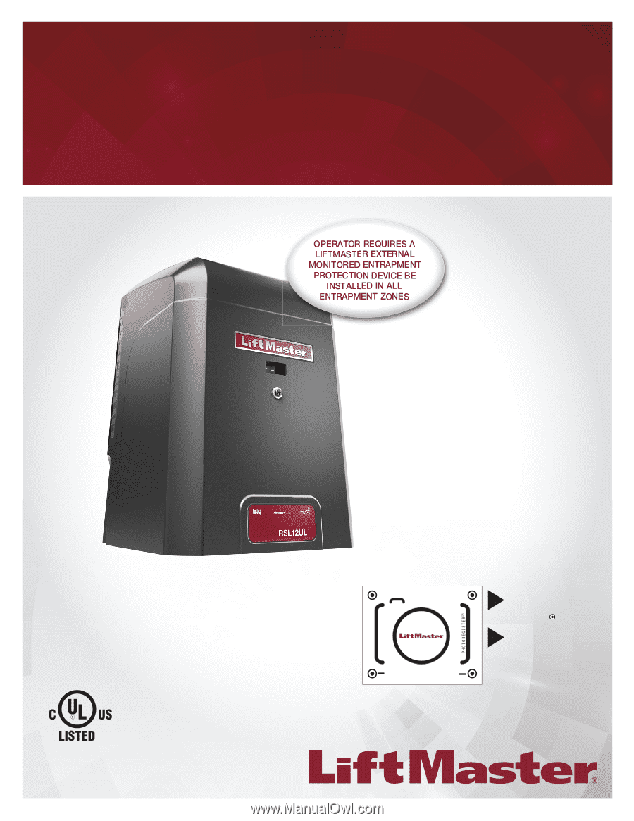
RESIDENTIAL DC
VEHICULAR SLIDE GATE OPERATOR
INSTALLATION MANUAL
LiftMaster
300 Windsor Drive
Oak Brook, IL 60523
Model
RSL12UL
•
THIS PRODUCT IS TO BE INSTALLED AND
SERVICED BY A TRAINED GATE SYSTEMS
TECHNICIAN ONLY.
•
This model is for use on vehicular passage
gates ONLY and not intended for use on
pedestrian passage gates.
•
This model is intended for use in Class I and II
vehicular slide gate applications.
•
Visit LiftMaster.com to locate a professional
installing dealer in your area.
•
This gate operator is compatible with MyQ
®
and Security+ 2.0
®
accessories.
Access installation and technical support
guides or register this product
Send it in
by texting the
photo to 71403.
Take a photo
of the
camera icon including
the points (
).
1.
2.
RSL12ULTECH