LiftMaster EL1SS EL1SS Installation and Programming Manual
LiftMaster EL1SS Manual
 |
View all LiftMaster EL1SS manuals
Add to My Manuals
Save this manual to your list of manuals |
LiftMaster EL1SS manual content summary:
- LiftMaster EL1SS | EL1SS Installation and Programming Manual - Page 1
EL1SS Telephone Entry System Installation and Programming Manual - LiftMaster EL1SS | EL1SS Installation and Programming Manual - Page 2
- LiftMaster EL1SS | EL1SS Installation and Programming Manual - Page 3
Master Code 12 TESTING 13 Test the Gate/Door Relays 13 Test the Telephone Connections 13 PROGRAMMING 14-20 General Instruction 14 Code Setup 15 Code Operation 15 Telephone Programming 16 Telephone Commands 17 Quick Reference 18-20 REPAIR PARTS 21 EL1SS MASTER CODE 21 WARRANTY 22 1 - LiftMaster EL1SS | EL1SS Installation and Programming Manual - Page 4
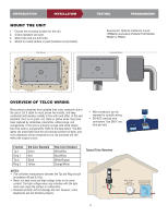
uninsulated 24 AWG twisted pair telephone wire 24 AWG twisted pair telephone wire 24 AWG twisted pair telephone wire See device specifications for WIRE SIZE 18 AWG 18 AWG 18 AWG 16 AWG 12 AWG NOTE: LiftMaster is not responsible for conflicts between the information listed in the above table and - LiftMaster EL1SS | EL1SS Installation and Programming Manual - Page 5
or 16 Vdc 2.5A Plug-In UL Listed Power Transformer (1) Bypass Board (1) Manual (1) DESCRIPTION OF THE PROCESSOR BOARD PROGRAMMING 1 9 6 7 5 10 13 12 Phone Output: Telephone return connection to home or office phones. 6 Line Input: Telephone input connection from "Telco" service provider. 7 - LiftMaster EL1SS | EL1SS Installation and Programming Manual - Page 6
Mount TESTING PROGRAMMING Accessories: Optional method to mount. LiftMaster Gooseneck Pedestal Post Models PED42 or PED64 Pedestal Mount data wires and cause the system to malfunction. • Reversed polarity will not damage the unit, however, some telephones will not function properly. Typical - LiftMaster EL1SS | EL1SS Installation and Programming Manual - Page 7
TUV WXYZ 0 # OPER Alarm System Position (Not Provided) Telco PHONE LINE RING TIP RING TIP Phone lines with DSL service. In order for the EL1SS to function normally a DSL filter is required to separate the DSL (digital) signal from the telephone service (POTS). 1. Install the splitter between - LiftMaster EL1SS | EL1SS Installation and Programming Manual - Page 8
MON 7 8 9 PQRS TUV WXYZ 0 # OPER Telco PHONE LINE RING TIP RING TIP WIRING THE UNIT WITHOUT A TELCO LINE The unit can be a stand alone system that allows communication between the unit and the resident's phones. Ringer Equivalence Number (REN) = 4 RING TIP RING TIP PHONE LINE 12:00 AM Dec - LiftMaster EL1SS | EL1SS Installation and Programming Manual - Page 9
INTRODUCTION INSTALLATION TESTING PROGRAMMING WIRING A GATE OPERATOR (NORMALLY OPEN) The gate operator can be connected to Relay 1 or Relay 2. See the Programming section for information about configuring Relays 1 and 2. • Wire connectors can be removed to simplify wiring. • DO NOT overload wire - LiftMaster EL1SS | EL1SS Installation and Programming Manual - Page 10
INTRODUCTION INSTALLATION WIRING A GATE OPERATOR (NORMALLY OPEN) & A DOOR STRIKE LOCK (NORMALLY OPEN) The door strike can be connected to Relay 1 or Relay 2. See the Programming section for information about configuring Relays 1 and 2. TESTING PROGRAMMING • Wire connectors can be removed to - LiftMaster EL1SS | EL1SS Installation and Programming Manual - Page 11
INTRODUCTION INSTALLATION TESTING PROGRAMMING WIRING A GATE OPERATOR (NORMALLY OPEN) & A MAGLOCK (NORMALLY CLOSED) The maglock can be connected to Relay 1 or Relay 2. See the Programming section for information about configuring Relays 1 and 2. DC Power Maglock NOTE: Install a 1N4001 diode or - LiftMaster EL1SS | EL1SS Installation and Programming Manual - Page 12
INTRODUCTION INSTALLATION TESTING WIRING A DOOR STRIKE LOCK (NORMALLY OPEN) The door strike can be connected to Relay 1 or Relay 2. See the Programming section for information about configuring Relays 1 and 2. AC or DC Power Door Strike NOTE: Do not use the unit's power supply for the door - LiftMaster EL1SS | EL1SS Installation and Programming Manual - Page 13
two problems: • Other equipment cannot introduce spikes, noise, surges, or dips into the power circuit. • The system's operation 18 AWG 18 AWG 18 AWG 16 AWG 12 AWG NOTE: LiftMaster is not responsible for conflicts between the information listed in the above EL1SS MUST be grounded. Dedicated Outlet - LiftMaster EL1SS | EL1SS Installation and Programming Manual - Page 14
Check the Power LED is illuminated. NOTE: Once power is applied, the EL1SS will begin to click to indicate that it is powered, and is waiting Master Code. The Master Code is used to unlock the programming functions of the EL1SS. The Master Code should not be distributed as a User Code. CLOSE THE - LiftMaster EL1SS | EL1SS Installation and Programming Manual - Page 15
: After the "Call" Button is pressed, the "Status" LED on the processor board will blink during transmission. 3. To test Relay 1 have someone answer the telephone and enter "*9" (Star + 9). The EL1SS will disconnect the call as soon as the relay is activated. To test Relay 2 have someone answer the - LiftMaster EL1SS | EL1SS Installation and Programming Manual - Page 16
. PROGRAMMING INSTRUCTION General Programming ENABLE TELCO (NO INTERCOM) MODE Telco Mode is using the main telephone line for the unit's communications to the house or complex. (NO TELCO) MODE Intercom Mode is a stand alone system that allows communication between the unit and a resident's phone - LiftMaster EL1SS | EL1SS Installation and Programming Manual - Page 17
Relay 2 be in Independent Mode. ENABLE VACATION (LOCK DOWN) MODE Locks the system from all User Code activity. 1. Enter the Master Code: ? ? ? Enter User Code to be deleted: ENTER A TEMPORARY (1 SHOT) USER CODE NUMBER The EL1SS holds 1 temporary User Code. 1. Enter the Master Code: ? ? ? ? 2. Enter - LiftMaster EL1SS | EL1SS Installation and Programming Manual - Page 18
and trigger corresponding channel. 1. Enter the Master Code: ? ? ? ? 2. Enter the Program Code: 5 6 To disengage party mode: Enter a valid code into the EL1SS keypad or enter "*5" into the local telephone. NOTE: Relay 2 must be in Independent Control Mode to engage Party Mode on relay 2. See page 13 - LiftMaster EL1SS | EL1SS Installation and Programming Manual - Page 19
DISABLE "DO NOT DISTURB" MODE Enter the command tone: 1 2 FROM FORWARDED TELEPHONE ACCEPT CALL FROM UNIT ON REMOTE TELEPHONE Enter the command tone: 0 Extend talk time: "Talk" or press 0 . If 9 (relay 1) or 5 (relay 2) is pressed, the EL1SS will automatically return to the telco line. 17 - LiftMaster EL1SS | EL1SS Installation and Programming Manual - Page 20
INTRODUCTION INSTALLATION TESTING PROGRAMMING KEYPAD PROGRAMMING PROGRAMMING DESCRIPTION OF TASK NUMBER 7 Delete User Code 9 Enter User Code 03 Enable Intercom (No-Telco) Mode 04 Enable Telco Mode 06 Speaker Volume 07 Microphone Sensitivity 09 Change the Master Code 51 Create - LiftMaster EL1SS | EL1SS Installation and Programming Manual - Page 21
1 Triggers Relay 1 User Code + 2 Triggers Relay 2 AUDIO FEEDBACK FROM THE EL1SS: 1 Low Tone Beep = Failure 2 Two High Tone Beeps = Valid sequence in negative tones (low single and triple fail tones). TELEPHONE PROGRAMMING PROGRAMMING NUMBER DESCRIPTION OF TASK **01 Enable Call Forwarding - LiftMaster EL1SS | EL1SS Installation and Programming Manual - Page 22
1 **11 Enable "Do Not Disturb" Mode Disabled **11 **12 Disable "Do Not Disturb" Mode **12 DIRECT COMMANDS FROM THE FORWARDED TELEPHONE PROGRAMMING DESCRIPTION OF TASK NUMBER FACTORY PROGRAMMING PROCEDURE SETTING 0 Accepts Call From The Unit 0 (Also Extends Talk Time) *5 Triggers Relay - LiftMaster EL1SS | EL1SS Installation and Programming Manual - Page 23
REPAIR PARTS PART NUMBER KSN1600341B K002B0821-1 K002B0799-3 K002B1597-1 K001D7121-1 K002B1598 K002B0799-4 K101C0232-1 DESCRIPTION Bypass board Transformer 16.5 VDC 2.5 A Keys Keypad Main Board Speaker Lock and keys Call Button EL1SS MASTER CODE Write down the Master Code and store in a secure - LiftMaster EL1SS | EL1SS Installation and Programming Manual - Page 24
: 1-800-528-2806 LiftMaster.com NOTICE: To comply with FCC and or Industry Canada rules (IC), adjustment or modifications of this receiver and/or transmitter are prohibited, except for changing the code setting or replacing the battery. THERE ARE NO OTHER USER SERVICEABLE PARTS. Tested to Comply - LiftMaster EL1SS | EL1SS Installation and Programming Manual - Page 25
EL1SS Système d'accès par téléphone Manuel d'installation et de programmation - LiftMaster EL1SS | EL1SS Installation and Programming Manual - Page 26
- LiftMaster EL1SS | EL1SS Installation and Programming Manual - Page 27
15 Fonctionnement du code 15 À partir du téléphoniques 16 Commande du téléphoniques 17 Référence rapide 18-20 PIÈCES DE RÉPARATION 21 CODE COMMUN DU EL1SS 21 GARANTIE 22 1 - LiftMaster EL1SS | EL1SS Installation and Programming Manual - Page 28
75 à 150 pieds 150 à 250 pieds 250 à 500 pieds CALIBRE DU CÂBLE D'ALIMENTATION CA 18 AWG 18 AWG 18 AWG 16 AWG 12 AWG REMARQUE : LiftMaster ne peut être tenue responsable des divergences entre les données du tableau ci-dessus et les exigences des codes de construction en vigueur localement - LiftMaster EL1SS | EL1SS Installation and Programming Manual - Page 29
INTRODUCTION INSTALLATION ESSAI PROGRAMMATION CONTENU DE LA BOÎTE D'EMBALLAGE Appareil (1) Clé (1) Transformateur d'alimentation enfichable de 12 Vca 20 VA ou 16 Vcc 2,5A VA homologué UL (1) Carte bypass (1) Manuel (1) DESCRIPTION DE LA CARTE PROCESSEUR 1 9 6 7 5 10 13 12 11 2 COM NO NC COM - LiftMaster EL1SS | EL1SS Installation and Programming Manual - Page 30
sur une surface solide ou par la poste (matériel non fourni). Accessoires : Méthode facultative pour monter. Modeles PED42 ou PED64 LiftMaster col de cygne piédestal après FWixaatilol Mn aouunmtur FPixeadteiosntaaluMpoéduensttal APERÇU DU CÂBLAGE DE TELCO Plusieurs compagnies de téléphone ont - LiftMaster EL1SS | EL1SS Installation and Programming Manual - Page 31
GHI JKL MON 7 8 9 PQRS TUV WXYZ 0 # OPER Emplacement du système d'alarme (non fourni) Telco PHONE LINE RING TIP RING TIP Lignes téléphoniques à service d'accès numérique (DSL). Pour que le EL1SS fonctionne normalement, un filtre DSL est nécessaire pour séparer le signal DSL (numérique) du - LiftMaster EL1SS | EL1SS Installation and Programming Manual - Page 32
INTRODUCTION INSTALLATION ESSAI PROGRAMMATION Ne jamais placer des câbles de données et des câbles à haute tension dans la même conduite. Les câbles à haute tension pourraient créer des interférences avec les câbles de données et entraîner un mauvais fonctionnement du système. CÂBLAGE DE L' - LiftMaster EL1SS | EL1SS Installation and Programming Manual - Page 33
INTRODUCTION INSTALLATION ESSAI PROGRAMMATION ACTIONNEUR DE BARRIÈRE (NORMALEMENT OUVERT) L'actionneur de barrière peut être raccordé au relai 1 ou au relai 2. Consulter la section Programmation pour les détails sur la configuration des relai 1 et 2. • Les connecteurs de fils peuvent être enlev - LiftMaster EL1SS | EL1SS Installation and Programming Manual - Page 34
INTRODUCTION INSTALLATION ESSAI PROGRAMMATION CÂBLAGE D'UN ACTIONNEUR DE BARRIÈRE (NORMALEMENT OUVERT) ET D'UNE GÂCHE DE BARRIÈRE (NORMALEMENT OUVERTE) La gâche peut être raccordée au relai 1 ou au relai 2. Consulter la section Programmation pour les détails sur la configuration des relais 1 et - LiftMaster EL1SS | EL1SS Installation and Programming Manual - Page 35
INTRODUCTION INSTALLATION ESSAI PROGRAMMATION CÂBLAGE D'UN ACTIONNEUR DE BARRIÈRE (NORMALEMENT OUVERT) ET D'UNE SERRURE MAGNÉTIQUE (NORMALEMENT FERMÉE) La serrure magnétique peut être raccordée au relai 1 ou au relai 2. Consulter la section Programmation pour les détails sur la configuration des - LiftMaster EL1SS | EL1SS Installation and Programming Manual - Page 36
INTRODUCTION INSTALLATION ESSAI PROGRAMMATION CÂBLAGE D'UNE GÂCHE (NORMALEMENT OUVERTE) La gâche peut être raccordée au relai 1 ou au relai 2. Consulter la section Programmation pour les détails sur la configuration des relais 1 et 2. Alimentation CA ou CC Gâche de barrière • Les connecteurs - LiftMaster EL1SS | EL1SS Installation and Programming Manual - Page 37
lectricité ou autres lignes souterraines de services publics , contacter les entreprises de services publics localiser souterraines AVANT de creuser Alimentation de 12 Vca (fournie) Le EL1SS DOIT être mis à la terre. Prise exclusive REMARQUE : LiftMaster ne peut être tenue responsable des - LiftMaster EL1SS | EL1SS Installation and Programming Manual - Page 38
, indiquant qu'il est sous tension et qu'il attend la programmation du code commun. Le code commun set à déverrouiller les fonctions programmées du EL1SS. Le code commun ne doit pas être distribué en tant que code d'utilisateur. FERMER LA L'APPAREIL Faites pivoter le panneau avant vers le haut - LiftMaster EL1SS | EL1SS Installation and Programming Manual - Page 39
d'autorisation , gardez le combiné du téléphone au moins 10 pieds de la EL1SS pendant les essais . 2. Appuyer sur la touche « Appel » sur le à quelqu'un de prendre l'appel et de saisir « *9 » (étoile + 9). Le EL1SS met fin à l'appel dès que le relai est activé. Pour l'essai du relai 2, demander - LiftMaster EL1SS | EL1SS Installation and Programming Manual - Page 40
INTRODUCTION INSTALLATION ESSAI PROGRAMMATION GÉNÉRALITÉS REMARQUE : Utiliser la touche ÉTOILE « * » pour annuler une saisie. INSTRUCTIONS DE PROGRAMMATION Programmation générale Programmation de code Programmation de relai Réglage du niveau SYNTAXE Code commun + commande Code commun + - LiftMaster EL1SS | EL1SS Installation and Programming Manual - Page 41
. 1. Saisir le code commun : ? ? ? ? 2. Saisir le code de programmation : 5 2 SAISIR UN CHIFFRE DE CODE D'UTILISATEUR TEMPORAIRE (UNE UTILISATION) Le EL1SS retient un code d'utilisateur temporaire. 1. Saisir le code commun : ? ? ? ? 2. Saisir le code de programmation : 5 1 L'appareil émettra un bip - LiftMaster EL1SS | EL1SS Installation and Programming Manual - Page 42
Saisir le code commun : ? ? ? ? 2. Saisir le code de programmation : 5 6 Pour désactiver le mode réception, saisir un code valide sur le clavier du EL1SS ou saisir « *5 » sur un appareil téléphonique local. REMARQUE : Le relai 2 doit être en mode de contrôle indépendant pour mettre en œuvre le mode - LiftMaster EL1SS | EL1SS Installation and Programming Manual - Page 43
une fois pour revenir à appeler à l'extérieur sur la ligne des telco, si 9 ou 5 ou n'est pas pressé. Si 9 (relais 1) ou 5 (relais 2) est enfoncée, le EL1SS reviendra automatiquement à la ligne de telco. 17 - LiftMaster EL1SS | EL1SS Installation and Programming Manual - Page 44
INTRODUCTION INSTALLATION ESSAI PROGRAMMATION PROGRAMMATION À L'AIDE DU CLAVIER CODE DE DESCRIPTION DE LA PROGRAMMATION FONCTION RÉGLAGE D'USINE MÉTHODE DE PROGRAMMATION 7 Suppression du code d'utilisateur Code commun (4 chiffres) + 7 + code d'utilisateur à supprimer (4 chiffres) 9 - LiftMaster EL1SS | EL1SS Installation and Programming Manual - Page 45
Code d'utilisateur + 1 Code d'utilisateur + 2 FONCTION Activation du relai 1 Activation du relai 2 MESSAGES SONORES DU EL1SS : 1 Tonalité basse = Échec 2 Bips = Séquence valide 3 Bips = Erreur ou séquence non valide REMARQUE : Utiliser la touche ÉTOILE « * » pour annuler une saisie. REMARQUE - LiftMaster EL1SS | EL1SS Installation and Programming Manual - Page 46
INTRODUCTION INSTALLATION ESSAI PROGRAMMATION COMMANDES DIRECTES À PARTIR D'UN TÉLÉPHONE LOCAL CODE DE PROGRAMMATION DESCRIPTION DE LA FONCTION RÉGLAGE D'USINE MÉTHODE DE PROGRAMMATION *5 Activation du relai 2 *5 *9 Activation du relai 1 *9 **04 Activation du mode réception ( - LiftMaster EL1SS | EL1SS Installation and Programming Manual - Page 47
-3 K002B1597-1 K001D7121-1 K002B1598 K002B0799-4 K101C0232-1 DESCRIPTION Carte bypass Transformateur 16.5 VCC 2.5 A Clés Clavier Carte principale Haut-parleur Serrure et clés Bouton d'appel CODE COMMUN DU EL1SS Noter le code commun et le conserver dans un endroit sûr. 21 - LiftMaster EL1SS | EL1SS Installation and Programming Manual - Page 48
instructions relatives à l'installation, à l'opération, à la maintenance et aux tests. Le non-respect de ces instructions assuré, à notre centre de service pour obtenir un remplacement sous OU RESPONSABILITÉ DE LA PART DU VENDEUR. LA PRÉSENTE FRAIS : 1-800-528-2806 LiftMaster.com AVIS : Les rè
-
 1
1 -
 2
2 -
 3
3 -
 4
4 -
 5
5 -
 6
6 -
 7
7 -
8
-
9
-
10
-
11
-
12
-
13
-
14
-
15
-
16
-
17
-
18
-
19
-
20
-
21
-
22
-
23
-
24
-
25
-
26
-
27
-
28
-
29
-
30
-
31
-
32
-
33
-
34
-
35
-
36
-
37
-
38
-
39
-
40
-
41
-
42
-
43
-
44
-
45
-
46
-
47
-
48
 |
 |

Installation and
Programming Manual
EL1SS
Telephone Entry System