Lenovo 7518B1U User Manual - Page 70
Install the new rear fan assembly by aligning the new rubber mounts with the corresponding holes in
 |
View all Lenovo 7518B1U manuals
Add to My Manuals
Save this manual to your list of manuals |
Page 70 highlights
4. Disconnect the rear fan assembly cable from the system fan connector on the system board. See "Locating parts on the system board" on page 11. 5. The rear fan assembly is attached to the chassis by four rubber mounts. Remove the rear fan assembly by breaking or cutting the rubber mounts and gently pulling the rear fan assembly out of the chassis. Note: The new rear fan assembly will have four new rubber mounts attached. Figure 43. Removing the rear fan assembly 6. Install the new rear fan assembly by aligning the new rubber mounts with the corresponding holes in the chassis and push the rubber mounts through the holes. 58 ThinkCentre User Guide
-
 1
1 -
2
-
3
-
4
-
5
-
6
-
7
-
8
-
9
-
10
-
11
-
12
-
13
-
14
-
15
-
16
-
17
-
18
-
19
-
20
-
21
-
22
-
23
-
24
-
25
-
26
-
27
-
28
-
29
-
30
-
31
-
32
-
33
-
34
-
35
-
36
-
37
-
38
-
39
-
40
-
41
-
42
-
43
-
44
-
45
-
46
-
47
-
48
-
49
-
50
-
51
-
52
-
53
-
54
-
55
-
56
-
57
-
58
-
59
-
60
-
61
-
62
-
63
-
64
-
 65
65 -
 66
66 -
 67
67 -
 68
68 -
 69
69 -
 70
70 -
 71
71 -
 72
72 -
 73
73 -
 74
74 -
 75
75 -
76
-
77
-
78
-
79
-
80
-
81
-
82
-
83
-
84
-
85
-
86
-
87
-
88
-
89
-
90
-
91
-
92
-
93
-
94
-
95
-
96
-
97
-
98
-
99
-
100
-
101
-
102
-
103
-
104
-
105
-
106
-
107
-
108
-
109
-
110
-
111
-
112
-
113
-
114
-
115
-
116
-
117
-
118
-
119
-
120
-
121
-
122
-
123
-
124
-
125
-
126
-
127
-
128
-
129
-
130
-
131
-
132
-
133
-
134
-
135
-
136
-
137
-
138
-
139
-
140
-
141
-
142
-
143
-
144
 |
 |

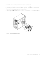
4. Disconnect the rear fan assembly cable from the system fan connector on the system board. See
“Locating parts on the system board” on page 11.
5. The rear fan assembly is attached to the chassis by four rubber mounts. Remove the rear fan assembly
by breaking or cutting the rubber mounts and gently pulling the rear fan assembly out of the chassis.
Note:
The new rear fan assembly will have four new rubber mounts attached.
Figure 43. Removing the rear fan assembly
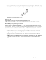
6. Install the new rear fan assembly by aligning the new rubber mounts with the corresponding holes in the
chassis and push the rubber mounts through the holes.
58
ThinkCentre User Guide