Lantronix xDirect xDirect - Quick Start Guide - Page 1
Lantronix xDirect Manual
 |
View all Lantronix xDirect manuals
Add to My Manuals
Save this manual to your list of manuals |
Page 1 highlights
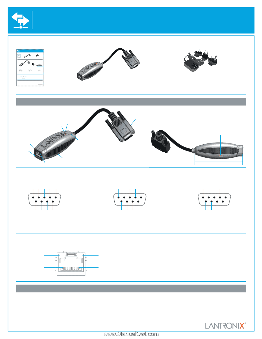
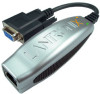
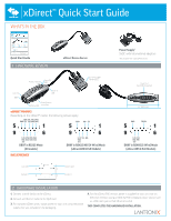
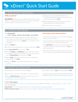
xDirect™ Quick Start Guide WHAT'S In THE BOX xDirect™ Quick Start Guide WHAT'S In THE BOX xDirect™ Quick Start Guide WHAT'S In THE BOX Quick Start Guide 1 HARDWARE REvIEW xDirect Device Server Power / Status LED Serial RX LED Serial Port DB9 Female (DCE) Link LED RJ45 Serial TX LED Reset Switch Activity LED on bottom xDIRECT PINOUTS Depending on the xDirect™ model, the following pinouts apply DTR TX RX DCD GND (in) (in) (out) (out) 5 1 GND RX+ TX- 5 1 9 6 9 6 5-15 CTS RTS DSR VDC (out) (in) (out) (in) DB9F in RS232 Mode (All models) 5-15 TX+ RXVDC (in) DB9F in RS422/485 (4-Wire) Mode (xDirect485 & PoE Models) RJ45 ETHERNET Link LED Contact 8 Activity LED Contact 1 Power Supply* 5vDC with International adapters *not included with xDirectPoE version Power Port (mini USB connector) 3.5" (88.9 mm) GND TX/RX- 5 1 9 6 5-15 TX/ VDC RX+ (in) DB9F in RS485 (2-Wire) Mode (xDirect485 & PoE Models) 2 HARDWARE InSTALLATIOn 1. Connect a serial device to the xDirect. 2. Connect an Ethernet cable to the RJ45 port. 3. For standard xDirect units, supply power to your unit using the power supply that was included in the packaging. 4. For the xDirectPoE version, power is supplied to your unit over an Ethernet interface using an 802.3af PoE compliant power source such as a PoE mid-span or PoE Ethernet switch. THIS COMPLETES THE HARDWARE INSTALLATION. Quick Start Guide 1 HARDWARE REvIEW xDirect Device Server Power Supply* 5vDC with International adapters *not included with xDirectPoE version Power / Status LED Serial RX LED Serial Port DB9 Female (DCE) Link LED RJ45 Serial TX LED Reset Switch Activity LED on bottom xDIRECT PINOUTS Depending on the xDirect™ model, the following pinouts apply DTR TX RX DCD GND (in) (in) (out) (out) 5 1 GND RX+ TX- 5 1 9 6 5-15 CTS RTS DSR VDC (out) (in) (out) (in) DB9F in RS232 Mode (All models) 9 6 5-15 TX+ RXVDC (in) DB9F in RS422/485 (4-Wire) Mode (xDirect485 & PoE Models) RJ45 ETHERNET Power Port (mini USB connector) 3.5" (88.9 mm) GND TX/RX- 5 1 9 6 5-15 TX/ VDC RX+ (in) DB9F in RS485 (2-Wire) Mode (xDirect485 & PoE Models) Link LED Contact 8 Activity LED Contact 1 2 HARDWARE InSTALLATIOn 1. Connect a serial device to the xDirect. 2. Connect an Ethernet cable to the RJ45 port. 3. For standard xDirect units, supply power to your unit using the power supply that was included in the packaging. 4. For the xDirectPoE version, power is supplied to your unit over an Ethernet interface using an 802.3af PoE compliant power source such as a PoE mid-span or PoE Ethernet switch. THIS COMPLETES THE HARDWARE INSTALLATION. Quick Start Guide 1 HARDWARE REvIEW xDirect Device Server Power Supply* 5vDC with International adapters *not included with xDirectPoE version Power / Status LED Serial RX LED Serial Port DB9 Female (DCE) Link LED RJ45 Serial TX LED Reset Switch Activity LED on bottom xDIRECT PINOUTS Depending on the xDirect™ model, the following pinouts apply DTR TX RX DCD GND (in) (in) (out) (out) 5 1 GND RX+ TX- 5 1 9 6 9 6 5-15 CTS RTS DSR VDC (out) (in) (out) (in) DB9F in RS232 Mode (All models) 5-15 TX+ RXVDC (in) DB9F in RS422/485 (4-Wire) Mode (xDirect485 & PoE Models) RJ45 ETHERNET Power Port (mini USB connector) 3.5" (88.9 mm) GND TX/RX- 5 1 9 6 5-15 TX/ VDC RX+ (in) DB9F in RS485 (2-Wire) Mode (xDirect485 & PoE Models) Link LED Contact 8 Activity LED Contact 1 2 HARDWARE InSTALLATIOn 1. Connect a serial device to the xDirect. 2. Connect an Ethernet cable to the RJ45 port. 3. For standard xDirect units, supply power to your unit using the power supply that was included in the packaging. 4. For the xDirect PoE version, power is supplied to your unit over an Ethernet interface using an 802.3af PoE compliant power source such as a PoE mid-span or PoE Ethernet switch. THIS COMPLETES THE HARDWARE INSTALLATION.
-
 1
1 -
 2
2
 |
 |