Lantronix XPort XPort - Data Sheet - Page 2
Hardware & Software Description - web pages
 |
View all Lantronix XPort manuals
Add to My Manuals
Save this manual to your list of manuals |
Page 2 highlights
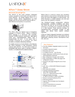
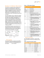
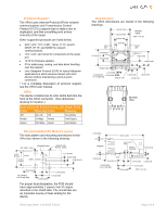
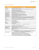
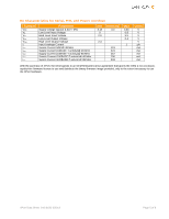
Hardware & Software Description The XPort is a complete solution (hardware and software) for web-enabling your edge devices. Packed into an RJ45 connector smaller than your thumb, this powerful device server comes with a 10BASE-T/100BASE-TX Ethernet connection, a reliable and proven operating system stored in flash memory, an embedded web server, a full TCP/IP protocol stack, and standards-based (AES) encryption. The XPort software runs on a DSTni-EX controller which has 256 KB of SRAM, 16 KB of boot ROM, and a MAC with integrated 10/100BASE-TX PHY. The XPort communicates to the edge device through a 3.3V serial interface and three generalpurpose programmable I/O pins. 512 KB of flash memory is included for storing firmware and web pages. The XPort runs on 3.3V, and has a built-in voltage supervisory circuit that will trigger a reset if the supply voltage drops to unreliable levels (2.7V). A built-in 1.8V regulator drives the processing core of the EX controller. An RJ45 Ethernet cable connects directly into an XPort. Ethernet magnetics, status LEDs, and shielding are built in. The XPort was designed to meet class B emissions levels, which makes the electromechanical integration very simple. MAGNETICS Tx LEDs Rx FLASH 25MHz DSTni-EX RJ45 CMOS IO RESET +3.3VDC PCB Interface The 8-pin PCB interface consists of 3.3V CMOS Serial In/Out, 3 Flow Control/Handshake/PIO pins, reset input, +3.3V power, and signal ground. All pins beside are 5V tolerant. Table 1 - PCB Interface Signals Signal Name GND Vcc Reset (In) Data OUT Data IN CP1 Pin 1 2 3 4 5 6 Function Circuit Ground +3.3V Power In External Reset In Serial Data Out Serial Data In CP1 can be configured as follows: • Flow control: RTS (Request to Send) output driven by DSTni's built-in UART for connection to CTS of attached device. • Programmable input/output: CP1 can be driven or read through software control, independent of serial port activity. CP2 can be configured as follows: • Modem control: DTR (Data Terminal Ready) output driven by DSTni's built- in UART for connection to DCD of CP2 7 attached device. • Programmable input/output: CP2 can be driven or read through software control, independent of serial port activity. CP3 can be configured as follows: • Flow control: CTS (Clear to Send) input read by DSTni's built-in UART for connection to RTS of attached device. • Modem control: DCD (Data Carrier CP3 8 Detect) input read by DSTni's built-in UART for connection to DTR of attached device. • Programmable input/output: CP3 can be driven or read through software control, independent of serial port activity. Ethernet Interface The 10/100 Ethernet magnetics, network status LEDs, and RJ45 connector are integrated into the XPort. Table 2 - Ethernet Interface Signals Signal Name TX+ TXRX+ RXNot Used Not Used Not Used Not Used SHIELD DIR Out Out In In Contact 1 2 3 6 4 5 7 8 Primary Function Transmit Data + Transmit Data - Receive Data + Receive Data - Terminated Terminated Terminated Terminated Chassis Ground XPort Data Sheet 910-815G 2/2013 Page 2 of 6
-
 1
1 -
 2
2 -
 3
3 -
 4
4 -
 5
5 -
 6
6
 |
 |
