Lantronix SLC 8000 Quick Start Guide
Lantronix SLC 8000 Manual
 |
View all Lantronix SLC 8000 manuals
Add to My Manuals
Save this manual to your list of manuals |
Lantronix SLC 8000 manual content summary:
- Lantronix SLC 8000 | Quick Start Guide - Page 1
the SLC 8000 Console Manager in order to receive notifications for firmware and documentation updates at www.lantronix.com/product-registration. WHAT'S IN THE BOX Quick Start Guide SLC 8000 Console Manager START Accessories For AC Supply Models: AC Power Cord included only For DC Supply Models - Lantronix SLC 8000 | Quick Start Guide - Page 2
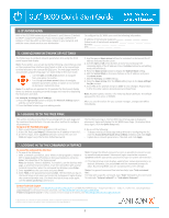
, is for restoring factory defaults. The default password for this action is 999999. After you save the values for your console manager, changes take effect immediately. 6. LOGGING IN TO THE WEB PAGE This section includes instructions for accessing both the web page and the command line interfaces - Lantronix SLC 8000 | Quick Start Guide - Page 3
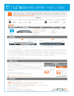
电源插口 第1组 第2组 第3组 LED指示灯 LCD SD Lantronix SLC 8000 IT SLC 8000 AUX Telnet SSH 56KINTMODEM- 01 IP IT CLI LCD 所有SLC 8000 UPS系统 • PBX PDU 2. 连接SLC 8000 PC 5 5 PC连接到SLC 8000 RJ45转DB9F 5类电缆。 9600 1 8 注意:SLC 8000 RS-232) 1. RTS 2. DTR 3. TX - Lantronix SLC 8000 | Quick Start Guide - Page 4
sysadmin PASS SLC 8000 SLC 8000 4 SLC 7 1 Telnet或SSH xx.xx.xx.xx(IP地 Telnet Telnet SSH 2. 输入sysadmin 3. 输入PASS admin quicksetup命令。) sysadmin 4 help command line"。 help help set network"或"help admin firmware"。 http://www.lantronix.com/support 或致电 (800
-
 1
1 -
 2
2 -
 3
3 -
 4
4
 |
 |
1
Only for models with RJ45 modules
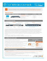
1. HARDWARE OVERVIEW
3. HARDWARE INSTALLATION
The front console port allows a dumb terminal or PC with terminal emula°on soſtware to
locally access management func°ons and connected devices.
The device ports allow simple and flexible connec°ons to serial devices using adapters and
a standard CAT5 cable. Connect one end of the CAT5 cable to the device port and the other
end to an adapter that a±aches to the serial console of the target system.
For example, to connect a PC to the console port of the SLC 8000, you only need the RJ45
to DB9F Adapter and a standard CAT5 cable which is supplied with the unit.
The default communica°on parameters for the device ports and console ports are:
9600 baud
• 1 stop bit
• 8 data bits
• No flow control
• No parity
Note:
SLC 8000 device ports are reversed by default, but are soſtware configurable.
2. CONNECTING THE SLC 8000
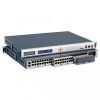
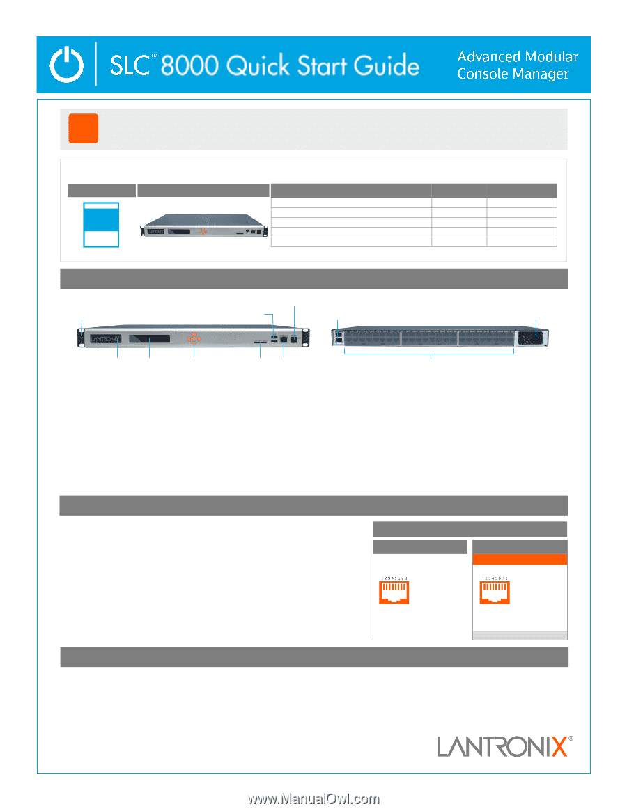
Front View
Back View
LCD
Keypad
SD Card
Console
Modem (Op°onal)
Dual USB
Ports
Device Ports (Modular)
10/100/1000
Dual Network Ports
Power Inlet
(Dual AC or Single AC or Dual DC)
Reversed by Default
1.
CTS
(In)
2.
DSR
(In)
3.
RX
(In)
4.
GND
5.
GND
6.
TX
(Out)
7.
DTR
(Out)
8.
RTS
(Out)
Indicator LED
Front
-
mid
-
rear
Moun°ng Bracket
1.
RTS
(Out)
2.
DTR
(Out)
3.
TX
(Out)
4.
GND
5.
GND
6.
RX
(In)
7.
DSR
(In)
8.
CTS
(In)
Console Port (RS
-
232)
Device Ports (RS
-
232)
!
Thank you for choosing Lantronix.
Please register the SLC 8000 Console Manager in order to receive
no°fica°ons for firmware and documenta°on updates at
www.lantronix.com/product
-
registra°on
.
Default
Pin Assignments
SLC 8000 Console Manager
Quick Start Guide
Accessories
Part Number
Quan°ty
For AC Supply Models:
AC Power Cord included only
500
-
041
-
ACC
1 for Single, 2 for Dual
For DC Supply Models:
DC Installa°on Kit only
083
-
152
-
ACC
1
RJ45 to RJ45, CAT5 Cable, 6.6 ſt (2 m)
200.0062
1
RJ45 to DB9F Adapter*
200.2070A
1
RJ45 Loopback Cable*
500
-
153
1
START
WHAT’S IN THE BOX
The Lantronix SLC 8000 Advanced Console Manager enables IT professionals to remotely and securely administer servers and networking equipment.
Leveraging the console or emergency management port built into most servers and networking equipment, the SLC 8000 provides remote access
anywhere, any°me. All that is required is an available console, AUX, or serial port on the a±ached equipment. Using in
-
band management, you can
manage equipment over the network from virtually any place, using familiar tools like Telnet or Secure Shell (SSH). Out
-
of
-
band management
provides access from a local terminal or through an internal modem (P/N 56KINTMODEM
-
01, sold separately). If a modem is used, dial
-
in access is
possible in the event that the IP network is unavailable. Once connected, the user has access to the server or IT equipment’s command line interface
(CLI) via the console port to perform maintenance or management tasks. The front LCD panel and keypad allow for quick and easy network
configura°on.
All SLC 8000 models are compa°ble with a variety of equipment, including:
• Switches
• Routers
• Firewalls
• Servers
• UPS systems
• PBX systems
• Telecom switches
• PDU
1.
Install the unit in a 19
-
inch rack.
Warning:
Do not block the air vents on the sides of the unit. If mounted in an enclosed rack, it is recommended that the rack have a ven°la°on fan.
2.
Connect the equipment to the numbered device ports on the back of the unit using the appropriate cables and adapters.
3.
If you installed the internal modem, connect a RJ11 cable between the front panel modem port on the SLC 8000 to your phone line.
4.
Connect the unit to the network using the upper network port (Ethernet 1).
5.
Connect the power cord and apply power.
6.
Wait about a minute and a half for the boot process to complete. When the boot process ends,
the SLC model name and clock appear on the LCD. Detected faults or process messages may also display.
Soſtware
Reversible
* Only included for models with RJ45 modules
Bay1
Bay2
Bay2