KitchenAid KVWB606HBS Installation Instructions - Page 10
Warning
 |
View all KitchenAid KVWB606HBS manuals
Add to My Manuals
Save this manual to your list of manuals |
Page 10 highlights
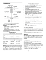
Make Electrical Connection WARNING 4. Run home power supply cable through strain relief into terminal box. A B Electrical Shock Hazard Disconnect power before servicing. Replace all parts and panels before operating. Failure to do so can result in death or electrical shock. 1. Disconnect power. 2. Remove terminal box cover. 3. Remove the knockout in the terminal box cover and install a UL listed or CSA approved ¹⁄₂" strain relief. A B A. Knockout B. Terminal box cover C. Screws (7) C C C C C D E F A. Home power supply cable B. UL listed or CSA approved strain relief C. Black wires D. UL listed wire connectors E. White wires F. Green (or bare) and yellowgreen ground wires 5. Use UL listed wire connectors and connect black wires (C) together. 6. Use UL listed wire connectors and connect white wires (E) together. WARNING Electrical Shock Hazard Electrically ground blower. Connect ground wire to green and yellow ground wire in terminal box. Failure to do so can result in death or electrical shock. 7. Connect green (or bare) ground wire from home power supply to yellow-green ground wire (F) in terminal box using UL listed wire connectors. 8. Tighten strain relief screw. 9. Install terminal box cover. 10. Check that all light bulbs are secure in their sockets. 11. Reconnect power. Optional Power Cord Kit Installations For optional power cord kit installations, follow the instructions supplied with the power cord kit. See the "Assistance or Service" section for information on ordering. NOTE: Use only with range hood cord connection kits that have been investigated and found acceptable for use with this model range hood. 10
-
 1
1 -
2
-
3
-
4
-
 5
5 -
 6
6 -
 7
7 -
 8
8 -
 9
9 -
 10
10 -
 11
11 -
 12
12 -
 13
13 -
 14
14 -
 15
15 -
16
-
17
-
18
-
19
-
20
-
21
-
22
-
23
-
24
-
25
-
26
-
27
-
28
-
29
-
30
-
31
-
32
 |
 |
