Invacare TDXSP2 Owners Manual 5
Invacare TDXSP2 Manual
 |
View all Invacare TDXSP2 manuals
Add to My Manuals
Save this manual to your list of manuals |
Invacare TDXSP2 manual content summary:
- Invacare TDXSP2 | Owners Manual 5 - Page 1
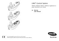
LiNX® Control System REM110, REM210, REM211, REM216, Supplement to power wheelchair user manual en Remote User Manual This manual MUST be given to the user of the product. BEFORE using this product, read this manual and save for future reference. - Invacare TDXSP2 | Owners Manual 5 - Page 2
whole or in part is prohibited without prior written permission from Invacare. Trademarks are identified by ™ and ®. All trademarks are owned by or licensed to Invacare Corporation or its subsidiaries unless otherwise noted. Invacare reserves the right to alter product specifications without further - Invacare TDXSP2 | Owners Manual 5 - Page 3
6.5 Service Inspection 37 6.5.1 Six Month Inspection 38 6.6 Cleaning 38 7 Troubleshooting 40 7.1 Fault diagnosis 40 7.1.1 Fault codes and diagnosis codes 40 7.2 OON ("Out Of Neutral 41 7.3 Drive inhibit indication 42 7.4 Cut-off voltage 43 8 Technical data 44 8.1 Technical specifications - Invacare TDXSP2 | Owners Manual 5 - Page 4
Quality of Service 48 9.4.1 Data Integrity 48 9.4.2 Safeguards and Redundancy 48 9.5 Wireless Coexistence 49 9.6 Cybersecurity 49 9.6.1 Cybersecurity Controls 49 9.6.2 User Actions 50 10 Warranty 51 10.1 Limited Warranty-US 51 10.2 Limited Warranty-Canada 51 10.3 Repair or Replacement 51 - Invacare TDXSP2 | Owners Manual 5 - Page 5
Invacare website. For the address and website see the back page of this manual. 1.2 Symbols Signal symbols and/or words are used in this manual recommendations and information for efficient, trouble-free use. This symbol identifies to the user manual for the power wheelchair base and for the seating - Invacare TDXSP2 | Owners Manual 5 - Page 6
is a variant of the LiNX remote module family, intended to allow powered wheelchair users to interact with the LiNX System. The REM110 allows control of drive functions, as well as providing an input for battery charging and a Bluetooth® interface for programming and diagnostics. 1.4.2 Intended Use - Invacare TDXSP2 | Owners Manual 5 - Page 7
and any additional instructional material such as user manual, service manuals or instruction sheets supplied with this product or optional equipment. 60101835-A Safety WARNING! Risk of Death, Injury or Damage Continued use of the product with damaged parts could lead to the product malfunctioning - Invacare TDXSP2 | Owners Manual 5 - Page 8
settings. - Always remove the LAK from the wheelchair when programming is complete. 8 WARNING! Risk of Serious Injury or Damage Use of unapproved accessories may result in serious injury or damage. - Invacare products are specifically designed and manufactured for use in conjunction with approved - Invacare TDXSP2 | Owners Manual 5 - Page 9
Injury or Damage Connector pins on cables connected to the power module can still be live even when the system is corrosion MUST be replaced immediately. - Wheelchairs that are used by incontinent users and/or are frequently exposed to water/liquids may require replacement of electrical components - Invacare TDXSP2 | Owners Manual 5 - Page 10
, pinching, chafing or other similar wear. - Replace any damaged cables immediately. Risk of damage to the mobility device There are no user-serviceable parts inside any case. - Do not open or disassemble any case. As a manufacturer of wheelchairs, Invacare endeavors to supply a wide variety of - Invacare TDXSP2 | Owners Manual 5 - Page 11
, or burning. Death, serious injury, or damage may occur due to fire. - DO NOT use the wheelchair other than its intended purpose. If the wheelchair starts smoking, sparking, or burning, discontinue using the wheelchair and seek service IMMEDIATELY. WARNING! Risk of Injury, Damage or Death Misuse of - Invacare TDXSP2 | Owners Manual 5 - Page 12
Damage Use of incorrect or improper replacement (service) parts may cause death, serious injury, or damage. - Replacement parts MUST match original Invacare parts. - ALWAYS provide the wheelchair serial number to assist in ordering the correct replacement parts. WARNING! Risk of Serious Injury Sharp - Invacare TDXSP2 | Owners Manual 5 - Page 13
Safety WARNING! Risk of Death, Serious Injury, or Damage Improperly connected joystick could cause loss of power resulting in death, serious injury, or damage. - Ensure the joystick is securely connected to controller. 60101835-A 13 - Invacare TDXSP2 | Owners Manual 5 - Page 14
EMC) Information 3.1 Electromagnetic Compatibility Refer to the power wheelchair base and seating system user manuals for more electromagnetic compatibility information for your mobility radiated fields and ESD, follow the wiring recommendations in the LiNX System Service Manual. 14 60101835-A - Invacare TDXSP2 | Owners Manual 5 - Page 15
4 Components 4.1 Overview Non-Expandable Remotes REM110 Expandable Remotes REM211 • Drive function REM210 • Drive function • Seating function (up to two actuators) REM216 Components • Drive function • Seating function (two or more actuators) • Drive function • Seating function (two or more - Invacare TDXSP2 | Owners Manual 5 - Page 16
LiNX® Control System 4.2 User interface REM110 4.3 User interface REM210 and REM211 Fig. 4-1 A ON/OFF button/Status indicator B Battery gauge C Speed dial D Horn E Joystick 16 The REM210 and REM211 remotes have the same user interface. The REM211 remote has a ring around the base of the joystick. - Invacare TDXSP2 | Owners Manual 5 - Page 17
D Connectivity indicator E Seating function selector F Drive/actuator status G Horn H Joystick I Drive function indicator J Drive function selector 60101835-A 4.4 User interface REM216 Components The REM216 remote has a ring around the base of the joystick. A ON/OFF button/Status indicator B - Invacare TDXSP2 | Owners Manual 5 - Page 18
there is a fault with the system when powered up, the status indicator flashes red. The number of flashes indicates the type of fault. Refer to 7.1.1 Fault codes and diagnosis codes, page 40. 4.6 Battery gauge The battery charging status is shown in the battery gauge. 18 Maximum driving range Green - Invacare TDXSP2 | Owners Manual 5 - Page 19
4.7 Labels on the product C A Recommendation to read the instruction manual before using the module. READ INSTALLATION D MANUAL BEFORE USE B IPx4 This is the enclosure's ingress protection rating. 60101835-A Components This is the WEEE symbol (Waste Electrical and Electronic Equipment - Invacare TDXSP2 | Owners Manual 5 - Page 20
logo • Dynamic Controls' website address • Dynamic Controls' part description Product label containing: • The product's bar code • The product's serial number • The product's part number The petrol pump indicates the battery charger input. Hardware and application firmware version label 1. Hardware - Invacare TDXSP2 | Owners Manual 5 - Page 21
lights up green and the battery gauge displays the current battery status. Refer to 4.6 Battery gauge, page 18. If there is a fault with the system when powering up, the status indicator indicates the fault with a series of red flashes. Refer to 7.1.1 Fault codes and diagnosis codes, page 40. If the - Invacare TDXSP2 | Owners Manual 5 - Page 22
so that the further the joystick is moved from the neutral position, the faster the wheelchair travels. If the user moves the joystick back to the neutral position, the wheelchair slows down and stops. If the user releases the joystick from any position other than the neutral position, the joystick - Invacare TDXSP2 | Owners Manual 5 - Page 23
. Refer to 5.4 Locking/unlocking the remote, page 23. 1. Press the ON/OFF button A for more than four seconds. 60101835-A When entering the locked state, the battery gauge indicates the transition by flashing LEDs red, amber and green (far left, middle and far right) three times. 23 - Invacare TDXSP2 | Owners Manual 5 - Page 24
locked state. During an unlock attempt, the battery gauge indicates the system is in a locked state middle and far right) until either the system is powered off, unlocked or the Sequence Timeout is reached. 5.5 sleep mode after a period of time without user activity. This period of time can be set - Invacare TDXSP2 | Owners Manual 5 - Page 25
moves as long as toggle switch is deflected. Stereo button switch The stereo button switch alternates powered seating functions of the following single power configurations: • Powered recline only • Powered seat tilt only • Center-mount elevating legrest (LNX) only 1. Make sure mobility device is on - Invacare TDXSP2 | Owners Manual 5 - Page 26
your provider. Powered seat tilt and Powered recline A (Forward) Powered seat tilt up B (Reverse) Powered seat tilt down C (Left) Powered recline up D (Right) Powered recline down 26 Powered seat tilt and LNX legrest A (Forward) Powered seat tilt up B (Reverse) Powered seat tilt down - Invacare TDXSP2 | Owners Manual 5 - Page 27
up D LNX down Powered seat tilt and elevating seat A Powered seat tilt up B Powered seat tilt down C Elevating seat up Powered seat tilt and Powered recline D Elevating seat down A Powered seat tilt up Dual powered elevating legrests B Powered seat tilt down A Left powered elevating legrest up - Invacare TDXSP2 | Owners Manual 5 - Page 28
System 5.6.2 Through the joystick Activating seating function Displayed symbols and meanings Not every wheelchair has all options. Powered seat tilt Powered recline 1. Press Seating function key A. • The wheelchair changes to seating function and the Drive/actuator status display C lights up - Invacare TDXSP2 | Owners Manual 5 - Page 29
Unspecified 5.6.3 Speed reduction and seating function inhibits The mentioned speed reduction and seating function inhibits do not apply to all Invacare wheelchair models. Speed reduction If the elevating seat has been adjusted above a certain point, the drive electronics considerably reduces the - Invacare TDXSP2 | Owners Manual 5 - Page 30
1 Drive function 2 Drive function 3 With the Drive function selector key you can choose between three different drive functions, that are configured by Invacare and can be fitted to your needs and requests by the provider. 5.8 Operating the lights If you drive outside, turn on the lights under - Invacare TDXSP2 | Owners Manual 5 - Page 31
Usage 5.10 Operating the direction indicators 1. Short press Light button A. The lights are turned on or off. 5.9 Operating the hazard lights 1. Short press Hazard lights button A. The hazard lights are turned on or off. 60101835-A Direction indicator left 1. Press Hazard lights button A for more - Invacare TDXSP2 | Owners Manual 5 - Page 32
off when losing power. This causes an charger that has been approved by Invacare. 32 WARNING! Risk of Injury or Damage Explosive gases can be generated while charging. To avoid flammable gas buildup and injury or damage due to explosion: - During charging, keep the wheelchair and battery charger - Invacare TDXSP2 | Owners Manual 5 - Page 33
Refer to the charger user manual, the power wheelchair base user manual and instructions supplied with the batteries for more information concerning charging the batteries. 1. Plug the battery charger into the remote's charger socket A. If the remote is powered up, the battery gauge indicates the - Invacare TDXSP2 | Owners Manual 5 - Page 34
. All LEDs on and the green LEDs flashing. 1. Disconnect battery charger. Low voltage warning The batteries are empty. Only one red LED on and flashing. 1. Power down wheelchair. 2. Charge batteries immediately. 34 5.13 Using the USB charger WARNING! Risk of injury If you use mobile phone while - Invacare TDXSP2 | Owners Manual 5 - Page 35
bung A. 2. Connect device with USB port. Replace bung when USB ports are not in use. The usage of the USB charger influences the drive range of the mobility device. For more information about the drive range, refer to chapter Technical Data in the user manual of your mobility device. 60101835-A 35 - Invacare TDXSP2 | Owners Manual 5 - Page 36
and casters, all types of batteries, joystick overlays and inductive rubberized protective boots. Invacare reserves the right to ask for any item back that has an alleged defect in workmanship. Refer to the Warranty section in this manual for specific warranty information. Refer to the Inspection - Invacare TDXSP2 | Owners Manual 5 - Page 37
Periodically • Check the joystick boot for damage. Contact your Invacare provider for replacement if damaged. • Check that all labels are present and legible. Replace if necessary. 6.5 Service Inspection Every six months take your wheelchair to a qualified technician for a thorough inspection and - Invacare TDXSP2 | Owners Manual 5 - Page 38
Actual items to be inspected during the service inspection may vary according to the specific wheelchair: 6.5.1 Six Month Inspection q Cables all loose cables and replace by following the recommendations outlined in the LiNX service manual. q Ensure proper operation of powered functions (drive, - Invacare TDXSP2 | Owners Manual 5 - Page 39
1. Use a cloth dampened with warm water and mild non-abrasive soap to clean this product. 2. Dry the surface with dry cloth. 3. DO NOT use solvents or kitchen cleaners. Maintenance 60101835-A 39 - Invacare TDXSP2 | Owners Manual 5 - Page 40
LiNX® Control System 7 Troubleshooting 7.1 Fault diagnosis If the electronic system shows a fault, use the following fault-finding guide to locate the fault. Ensure that the drive electronics system is powered up before starting any diagnosis. If the status display is OFF: • Check whether the drive - Invacare TDXSP2 | Owners Manual 5 - Page 41
the mobility device in freewheel mode" in the user manual of your wheelchair. • Contact your provider. 60101835-A Flash code 6 7 Fault description Right magnetic brake fault Module fault (other than remote module) Possible action Troubleshooting • Check cables and connectors. • Check right - Invacare TDXSP2 | Owners Manual 5 - Page 42
the seating motions operate normally. 7.3 Drive inhibit indication The drive inhibit mode ensures that the wheelchair does not drive when connected to the charger. Drive inhibit mode is indicated by the battery gauge with a right-to-left chase sequence. The chase sequence continues until the fault - Invacare TDXSP2 | Owners Manual 5 - Page 43
When the battery voltage decreases below the battery cut-off voltage: • the status indicator flashes red (Flash code 2, refer to 7.1.1 Fault codes and diagnosis codes, page 40), • the red LED on the battery gauge flashes, • the horn sounds once every ten seconds. 60101835-A Troubleshooting 43 - Invacare TDXSP2 | Owners Manual 5 - Page 44
8 Technical data 8.1 Technical specifications Mechanical specifications Permissible operating, storage and humidity • -40 °F (-40 °C)- +149 °F (+65 °C) • 0 ... 90 %RH IPX41 Operating forces Joystick Power button Speed dial Horn button REM110/REM210/REM211/REM216 • 1.9 N • 2.5 N • 1.2 N • 2.5 N - Invacare TDXSP2 | Owners Manual 5 - Page 45
Electrical specifications Parameter Operating voltage (Vbatt) Idle current Quiescent current (power off) Min. • 17 - Nominal • 24 • 56 - Max. • 34 • 0.23 Technical data Units •V • mA at 24V • mA at 24V 60101835-A 45 - Invacare TDXSP2 | Owners Manual 5 - Page 46
100 ms 6 ms Network Topology Scatternet Power Consumption 5 mW Service Discovery Yes Profile Concept Yes 9.2 Intended Wireless (Electromagnetic) Environment The intended environments for the LiNX wheelchair are defined as the users home, assisted living facilities, nursing 60101835 - Invacare TDXSP2 | Owners Manual 5 - Page 47
The system transmits wheelchair-specific diagnostic information to an Apple iOS device. This information helps with the technical support of the wheelchair. The information provides the status of the wheelchair electronics, including: • The state of charge of the battery, • Active and historical - Invacare TDXSP2 | Owners Manual 5 - Page 48
of the user's PC cursor. Similar conditions exist with normal off-the-shelf USB or wireless PC mice when their batteries are low. 48 Loss of diagnostic data transmitted could result in a gap in historical information presented to a service technician. Errors in the wheelchair-specific diagnostic - Invacare TDXSP2 | Owners Manual 5 - Page 49
when subjected to a frequency of 2.44 GHz. The function of the wheelchair was not impacted by the disruption of the LiNX Access Key wireless using the Programming and Diagnostic tools by a healthcare professional or a service technician with a LiNX Access Key (LAK) connected to the charging - Invacare TDXSP2 | Owners Manual 5 - Page 50
to take any specific actions in order to assure cybersecurity of the LiNX system. However, should the user be concerned about the Bluetooth connection for any reason, the user can switch off the Bluetooth functionality by powering down the system. The user also has the option to power up the system - Invacare TDXSP2 | Owners Manual 5 - Page 51
excluding batteries), motors, powered seating actuators, gearboxes. Invacare batteries covered by the Warranty. Such repair or replacement does not include any labor or shipping charges incurred by Invacare in the replacement and/or repair of any such component or battery. For Warranty service - Invacare TDXSP2 | Owners Manual 5 - Page 52
by Invacare. The Warranty does not apply to problems arising from normal wear and tear or failure to adhere to the product instructions. A change in operating noise, particularly relative to motors and gearboxes does not constitute a failure or defect and will not be repaired or replaced as - Invacare TDXSP2 | Owners Manual 5 - Page 53
Notes - Invacare TDXSP2 | Owners Manual 5 - Page 54
Notes - Invacare TDXSP2 | Owners Manual 5 - Page 55
Notes - Invacare TDXSP2 | Owners Manual 5 - Page 56
570 Matheson Blvd E Unit 8 Mississauga Ontario, L4Z 4G4 Canada Tel: 800-668-5324 www.invacare.ca USA One Invacare Way Elyria, Ohio USA 44035 Tel: 440-329-6000 Tel: 800-333-6900 www.invacare.com New Zealand Invacare New Zealand Ltd 4 Westfield Place, Mt Wellington 1060 New Zealand Tel: 0800 468 222
-
 1
1 -
 2
2 -
 3
3 -
 4
4 -
 5
5 -
 6
6 -
 7
7 -
8
-
9
-
10
-
11
-
12
-
13
-
14
-
15
-
16
-
17
-
18
-
19
-
20
-
21
-
22
-
23
-
24
-
25
-
26
-
27
-
28
-
29
-
30
-
31
-
32
-
33
-
34
-
35
-
36
-
37
-
38
-
39
-
40
-
41
-
42
-
43
-
44
-
45
-
46
-
47
-
48
-
49
-
50
-
51
-
52
-
53
-
54
-
55
-
56
 |
 |

LiNX® Control System
REM110, REM210, REM211, REM216, Supplement to
power wheelchair user manual
en
Remote
User Manual
This manual MUST be given to the user of the product.
BEFORE using this product, read this manual and save for future reference.