Invacare 9670 Owners Manual
Invacare 9670 Manual
 |
View all Invacare 9670 manuals
Add to My Manuals
Save this manual to your list of manuals |
Invacare 9670 manual content summary:
- Invacare 9670 | Owners Manual - Page 1
or not level. • After any adjustments, repair or service and before use, make sure all attaching hardware is permanent damage may occur. Set-Up NOTE: These instructions are valid for all types of transfer benches, support. Secure all in place with two locknuts. End Rail Height Channel Guides - Invacare 9670 | Owners Manual - Page 2
shall be limited to such repair and/or replacement. For warranty service, please contact the dealer from whom you purchased your Invacare product. THE WARRANTY SHALL NOT APPLY TO PROBLEMS ARISING FROM NORMAL WEAR OR FAILURE TO ADHERE TO THE ENCLOSED INSTRUCTIONS. IN ADDITION, THE FOREGOING WARRANTY - Invacare 9670 | Owners Manual - Page 3
taquets Installation REMARQUE: ces instructions sont valides pour les bancs supports. REMARQUE: on entendra un clic audible. • Pour retirer les bras de siège, pousser les boutons à ressort et soulever le bras. des pattes Trous Guides services Invacare, veuillez consulter www.invacare.com. Part No 1148079 - Invacare 9670 | Owners Manual - Page 4
avez acheté votre produit Invacare. Si vous n'êtes pas satisfait du service, écrire directement à Invacare à l'adresse inscrite à la dernière NE S'APPLIQUE PAS AUX PROBLÈMES DÉCOULANT DE L'USURE NORMALE, OU SI LES INSTRUCTIONS CI-INCLUSES N'ONT PAS ÉTÉ RESPECTÉES. DE PLUS, LA PRÉSENTE GARANTIE NE
-
 1
1 -
 2
2 -
 3
3 -
 4
4
 |
 |

For more information regarding Invacare products, parts, and services, please visit www.invacare.com
Part No 1148079
1
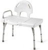
Transfer Bench
Transfer Bench
SAVE THESE INSTRUCTIONS
NOTE: Check ALL parts for shipping damage. If shipping damage is noted, DO NOT use. Contact carrier/dealer for further instruction.
±
WARNING
•
DO NOT install or use this equipment without first reading and understanding this instruction sheet. If you are unable to understand the warnings,
cautions or instructions, contact a healthcare professional, dealer or technical personnel, before attempting to install this equipment - otherwise,
injury or damage may occur.
•
The transfer bench backrest and armrest MUST be installed before using the transfer bench.
•
DO NOT submerge seat in water otherwise damage to seat may result.
•
Check rubber tips for rips, tears, cracks or wear. If any of these conditions exist, replace rubber tips IMMEDIATELY.
•
Users with limited physical capabilities should be supervised or assisted when using the transfer bench.
•
Use seat arm only to assist in transfers. DO NOT attempt to use seat arm to assist in standing in tub, otherwise tipping of the transfer bench could
result.
•
This product should only be used with tub floors wider than 18-5/8 inches.
•
ALWAYS observe the weight limit on the labeling of this product. Check that all labels are present and legible. Replace if necessary.
•
Most tub floors are higher than the bathroom floor. Before using, ensure that the four legs of the transfer bench inside the tub are adjusted to the
same height and the two legs outside the tub are adjusted to the same height, so as to achieve a level seat. If the transfer bench has suction feet, apply
all suction feet to the inside tub surface. DO NOT use the transfer bench if wobbly, unstable, or not level.
•
After any adjustments, repair or service and before use, make sure all attaching hardware is securely tightened - otherwise injury or damage may
result.
•
The seat arm is NOT intended to support the total body weight of the user.
•
Model 9670 only - Make sure that the compression buttons on the back support tabs are completely visible through the notches on the back of the
seat before use.
CAUTION
•
If the transfer bench has suction feet, pull the tabs up to release the feet from the tub. Otherwise, permanent damage may occur.
Set-Up
NOTE: These instructions are valid for all types of transfer benches, although models vary.
Attaching the Back
Perform one of the following depending on bench type:
Model 9670 (DETAIL “A”):
1.
Push the tabs on the bottom of the back into the holes in the seat until the
compression buttons are completely visible through the notches on the
back of the seat.
Other transfer bench models (DETAIL “B”):
1.
Position the back support on the back support tubes and secure with four
mounting screws.
2.
Align seat support tubes with the four channel guides on the underside
of the frame and slide them through the channel guides until the snap
buttons fully protrude through the channel guide holes.
NOTE: An audible
ʺ
click
ʺ
will be heard.
Assembly, Installation and Operating Instructions
Attaching the Seat Pads/Seat
Perform the following depending on bench type:
Model 9670 (DETAIL “A”):
1.
Position the seat and leg frames together upside down on a level surface
(snap buttons facing inward).
2.
Attach the leg frames to the seat with mounting screws.
Other transfer bench models (DETAIL “B”):
1.
Position the seat pads and leg frames together upside down on a level
surface.
2.
Secure the end rail to the leg frame with the short mounting screws and
locknuts.
3.
Repeat STEPS 1
‐
2 to attach the other end rail on the opposite end of the
leg frames.
4.
Align the mounting holes in the seat pads with the mounting holes in the
leg frames and attach with mounting screws.
Attaching the Seat Arm
Perform the following depending on bench type:
Model 9670 (DETAIL “A”):
1.
On the end of the transfer bench with the soap dish, remove and retain
the hardware that secures the seat to the leg frame.
2.
Position the seat arm against the leg frame and into the slots in the seat.
Thread the mounting screws through the seat arm, the leg frame and the
seat support. Secure all in place with two locknuts.
Other transfer bench models (DETAIL “B”):
1.
Remove and retain the hardware that secures the end rail to the leg
frame.
2.
Position the end rail against the leg frame. Position the seat arm on the
outside of the leg frame.
3.
Secure the end rail and seat arm to the leg frame with two mounting
screws and locknuts.
4.
Model 98071 only:
• To install the seat arm, push the snap buttons on the seat arm and
insert into the brackets. Make sure that the snap buttons fully protrude
through the holes in the brackets.
NOTE: An audible
ʺ
click
ʺ
will be heard.
• To remove the seat arm, push the snap buttons in and pull up.
Adjusting Transfer Bench Height
±
WARNING
Make sure that all snap buttons protrude fully through the height
adjustment holes in the leg extensions before use, otherwise injury or
damage may occur.
1.
Press the snap button on the leg frame.
2.
Slide the leg extension up or down to the desired height until snap
button protrudes fully through the height adjustment hole in the leg
extension.
NOTE: An audible
ʺ
click
ʺ
will be heard.
3.
Repeat STEPS 1 and 2 for the other legs as required.
Back
Seat Arm
Soap Dish
Leg Extension
Seat
Leg Frame
Tabs (insert into holes in seat)
Back
Support
Seat Arm
Back Support
Tubes
Seat Pads
Snap Button
Height
Adjustment Holes
End
Rail
Leg
Extension
Leg
Frame
Channel Guides
DETAIL “B” - OTHER TRANSFER BENCH MODELS
MODEL 98071
MODEL 9871
Back
Support
Seat Arm
Back Support
Tubes
Seat Pads
Leg
Extension
Height
Adjustment
Holes
Channel Guides
Leg
Frame
End
Rail
Suction
Feet
DETAIL “A” - TRANSFER BENCH MODEL 9670