Intel BOXD845GVSR Product Specification - Page 87
Table 55., Primary/Secondary IDE Master/Slave Submenus
 |
View all Intel BOXD845GVSR manuals
Add to My Manuals
Save this manual to your list of manuals |
Page 87 highlights
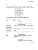
BIOS Setup Program Table 55. Primary/Secondary IDE Master/Slave Submenus (continued) Feature Block Mode PIO Mode DMA Mode S.M.A.R.T. Cable Detected Options • Disabled • Auto (default) • Auto (default) • 0 • 1 • 2 • 3 • 4 • Auto (default) • SWDMA0 • SWDMA1 • SWDMA2 • MWDMA0 • MWDMA1 • MWDMA2 • UDMA0 • UDMA1 • UDMA2 • UDMA3 • UDMA4 • UDMA5 • Auto (default) • Disabled • Enabled No options Description Disabled = Data transfers to/from the device occur one sector at a time. Auto = Data transfers to/from the device occur multiple sectors at a time if the device supports block mode transfers. (This item is read-only unless Type is set to User.) Specifies the PIO mode. (This item is read-only unless Type is set to User.) Specifies the DMA mode for the drive. Auto = Auto-detected SWDMAn = Single Word DMAn SWDMAn = Multi Word DMAn UDMAn = Ultra DMAn (This item is read-only unless Type is set to User.) Enables/disables S.M.A.R.T. (Self-Monitoring, Analysis, and Reporting Technology). (This item is read-only unless Type is set to User.) Displays the type of cable connected to the IDE interface: 40-conductor or 80-conductor (for ATA-100 peripherals). Note: If an LS-120 drive is attached to the system, a row entitled ARMD Emulation Type will be displayed in the above table. The BIOS will always recognize the drive as an ATAPI floppy drive. The ARMD Emulation Type should always be set to Floppy. 87
-
 1
1 -
2
-
3
-
4
-
5
-
6
-
7
-
8
-
9
-
10
-
11
-
12
-
13
-
14
-
15
-
16
-
17
-
18
-
19
-
20
-
21
-
22
-
23
-
24
-
25
-
26
-
27
-
28
-
29
-
30
-
31
-
32
-
33
-
34
-
35
-
36
-
37
-
38
-
39
-
40
-
41
-
42
-
43
-
44
-
45
-
46
-
47
-
48
-
49
-
50
-
51
-
52
-
53
-
54
-
55
-
56
-
57
-
58
-
59
-
60
-
61
-
62
-
63
-
64
-
65
-
66
-
67
-
68
-
69
-
70
-
71
-
72
-
73
-
74
-
75
-
76
-
77
-
78
-
79
-
80
-
81
-
 82
82 -
 83
83 -
 84
84 -
 85
85 -
 86
86 -
 87
87 -
 88
88 -
 89
89 -
 90
90 -
 91
91 -
 92
92 -
93
-
94
-
95
-
96
-
97
-
98
-
99
-
100
-
101
-
102
-
103
-
104
-
105
-
106
-
107
-
108
-
109
-
110
 |
 |
