Honeywell NX4L1 Installation Guide - Page 29
Default, Function, NetAXS Board, Relay, Power Distribution, Output Board Relay, Output Board DIP,
 |
View all Honeywell NX4L1 manuals
Add to My Manuals
Save this manual to your list of manuals |
Page 29 highlights
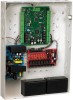
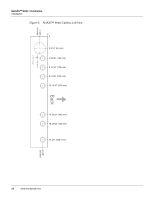
NetAXS™ NX4L1 Installation Installation Each Power Distribution Output relay has a 2 Amp Positive Temperature Coefficient (PTC)-protected output and a yellow indicator LED. The yellow LED illuminates if the PTC is active. Each relay also has a red indicator LED, which indicates the relay state. If the relay is active, the LED is illuminated. For field wiring, attach the negative terminal of the load to the NEG output terminal of the Power Distribution Output relay. Attach the positive load terminal to either the Normally Open or Normally Closed terminal of the Power Distribution Output relay. Refer to Figure 9 on page 20 for a wiring example. Caution: The cable used must be sized for the current load and should be shielded. The cable shield should be grounded at the panel only. Grounding at both ends can cause ground loops which can be disruptive. Do not bundle these wires with communication, reader, or supervised input wiring. To minimize premature contract failure and increase system reliability, a contact protection circuit (HAS part number S-4) is highly recommended. Locate the protection circuit as close as possible to the load. The Power Distribution Output board can be connected to an external Fire Alarm Control Panel (FACP). When the FACP input signal is active, it will turn off the selected relays on the Power Distribution Output board. An eight-position DIP switch is used to select which Power Distribution Output relays are affected by the FACP input. To make an output respond to the FACP input, move the associated DIP switch to the OFF position. To have the relay ignore the state of the FACP input, move the DIP switch to the ON position. The Power Distribution Output board has a green LED that indicates the status of the external FACP input. The LED will turn on when the input is active and turn off when inactive. Table 4: NetAXS Relay and Power Distribution Board DIP Switch Associations Default Function NetAXS Board Relay Power Distribution Power Distribution Output Board Relay Output Board DIP Switch Door 1 1 1 1 Door 2 2 2 2 Door 3 3 3 3 Door 4 4 4 4 Auxiliary 5 5 5 Auxiliary 6 6 6 Auxiliary 7 7 7 Auxiliary 8 8 8 NetAXS Access Control Unit NX4L1 Installation Guide, Document 7-901099, Revision A 19
-
 1
1 -
2
-
3
-
4
-
5
-
6
-
7
-
8
-
9
-
10
-
11
-
12
-
13
-
14
-
15
-
16
-
17
-
18
-
19
-
20
-
21
-
22
-
23
-
 24
24 -
 25
25 -
 26
26 -
 27
27 -
 28
28 -
 29
29 -
 30
30 -
 31
31 -
 32
32 -
 33
33 -
 34
34 -
35
-
36
-
37
-
38
-
39
-
40
-
41
-
42
-
43
-
44
-
45
-
46
-
47
-
48
-
49
-
50
-
51
-
52
-
53
-
54
-
55
-
56
-
57
-
58
-
59
-
60
-
61
-
62
-
63
-
64
-
65
-
66
-
67
-
68
-
69
-
70
-
71
-
72
-
73
-
74
-
75
-
76
-
77
-
78
-
79
 |
 |
