Honeywell MK1690-61A38 User Manual - Page 40
Cable Connector Configurations (Host End), DTR Input/Light Pen Source
 |
View all Honeywell MK1690-61A38 manuals
Add to My Manuals
Save this manual to your list of manuals |
Page 40 highlights
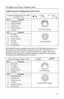
SCANNER AND CABLE TERMINATIONS Cable Connector Configurations (Host End) "Standard" PowerLink Cable 53-53000-3 Coiled Pin Function 1 Shield Ground 2 RS232 Transmit Output 3 RS232 Receive Input 4 DTR Input/Light Pen Source 5 Power/Signal Ground 6 Reserved 7 CTS Input 8 RTS Output 9 +5VDC 95 61 9-Pin D-Type Connector Stand Alone Keyboard PowerLink Cable 53-53020-3 Pin Function 1 PC Data 2 NC 3 Power Ground 4 +5VDC PC Power to KB 5 PC Clock 6 NC 21 4 3 65 6-Pin Male Mini-DIN Connector USB Power/Communication Cable 53-53213-N-3, 53-53214-N-3 or 53-53235-N-3 Pin Function 1 PC +5V/V_USB 2 D- 3 D+ 4 Ground Shield Shield USB Type A Locking with Power USB Non-Locking 36
-
 1
1 -
2
-
3
-
4
-
5
-
6
-
7
-
8
-
9
-
10
-
11
-
12
-
13
-
14
-
15
-
16
-
17
-
18
-
19
-
20
-
21
-
22
-
23
-
24
-
25
-
26
-
27
-
28
-
29
-
30
-
31
-
32
-
33
-
34
-
 35
35 -
 36
36 -
 37
37 -
 38
38 -
 39
39 -
 40
40 -
 41
41 -
 42
42 -
 43
43 -
 44
44 -
 45
45 -
46
-
47
-
48
-
49
-
50
-
51
-
52
 |
 |

36
S
CANNER AND
C
ABLE
T
ERMINATIONS
Cable Connector Configurations (Host End)
“Standard” PowerLink Cable
53-53000-3
Coiled
Pin
Function
1
Shield Ground
2
RS232 Transmit Output
3
RS232 Receive Input
4
DTR Input/Light Pen Source
5
Power/Signal Ground
6
Reserved
7
CTS Input
8
RTS Output
9
+5VDC
Stand Alone Keyboard PowerLink
Cable
53-53020-3
Pin
Function
1
PC Data
2
NC
3
Power Ground
4
+5VDC PC Power to KB
5
PC Clock
6
NC
USB Power/Communication Cable
53-53213-N-3, 53-53214-N-3 or
53-53235-N-3
Pin
Function
1
PC +5V/V_USB
2
D-
3
D+
4
Ground
Shield Shield
USB Type A
Locking with Power
USB
Non-Locking
9-Pin D-Type Connector
9
5
6
1
4
2
1
3
6
5
6-Pin Male Mini-DIN Connector