Honeywell C7089U1006 Owner's Manual - Page 2
Caution - outdoor sensor
 |
UPC - 085267256834
View all Honeywell C7089U1006 manuals
Add to My Manuals
Save this manual to your list of manuals |
Page 2 highlights
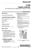
C7089 OUTDOOR SENSOR Wiring CAUTION Electrical Interference (Noise) Hazard. Can cause erratic system operation. Keep wiring at least one foot away from large inductive loads such as motors, line starters, lighting ballasts and large power distribution panels. Use shielded cable to reduce interference when rerouting is not possible. IMPORTANT Erratic temperature readings from a sensor can occur as a result of any of the wiring practices described below. Avoid these practices to assure correct operation. Use shielded cable to reduce interference if rerouting of sensor wiring is not possible. - Be sure wires have a cable separate from the thermostat cable. - Do not route temperature sensor wiring with building power wiring, next to control contactors or near light dimming circuits, electric motors or welding equipment. - Avoid poor wiring connections. - Avoid intermittent or missing building earth ground. Wiring must comply with applicable codes, ordinances and regulations: 1. Wire the C7089 Outdoor Sensor to S1 and S2 terminals on the thermostat. If leadwire provided with C7089 is not long enough (60 in.), run a cable to a hole at C7089 location. a. Using color-coded, 18-gauge thermostat wire is recommended. For example of general wiring of C7089, see Fig. 2. b. Pigtail wiring can be used. 2. Mount C7089 in its mounting clip. 3. Plug wiring hole using nonhardening caulk or putty. 1 C7089 WIRING HOLE THROUGH 2 STRUCTURE CAUTION Electrical Shock Hazard. Can cause electrical shock or equipment damage. Disconnect power supply before connecting wiring. 1 USE APPROPRIATE MOUNTING MEANS FOR THE TYPE OF STRUCTURE. 2 PLUG WIRING HOLE WITH NON-HARDENING CAULK OR PUTTY. M19970 Fig. 2. Wiring C7089 Outdoor Sensor to thermostat. 69-1709EFS 2
-
 1
1 -
 2
2 -
 3
3 -
 4
4 -
 5
5 -
 6
6 -
 7
7 -
 8
8 -
9
-
10
-
11
-
12
 |
 |
