HP T1500J HP T750 G2, HP T750J, HP T1000 G3, HP T1000J, HP T1500 G3, and HP T1 - Page 12
For HP T750 G2, HP T750J, and HP T1000 G3 models, carefully remove the metal - t1500 g3 ups battery replacement
 |
View all HP T1500J manuals
Add to My Manuals
Save this manual to your list of manuals |
Page 12 highlights
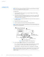
INSTALLATION 3 Slide up and remove the metal battery cover (see Figure 3). Do not remove any screws. NOTE: For HP T750 G2, HP T750J, and HP T1000 G3 models, carefully remove the metal battery cover to avoid damaging the battery disconnect blades. HP T750 G2 HP T750J, and HP T1000 G3 HP T1000J HP T1500 G3, and HP T1500J Figure 3 Removing the Battery Cover 4 Remove the protective label from the internal battery connector (see Figure 4). Figure 4 Removing the Protective Label 5 Connect the red wire to the positive ()) battery connector (see Figure 5). NOTE: A small amount of arcing may occur when connecting the batteries. This is normal and does not damage the unit or present any safety concern. Figure 5 Connecting the Internal Battery Connector 6 Replace the metal battery cover. 7 Replace the UPS front bezel. HP T750 G2, HP T750J, HP T1000 G3, HP T1000J, HP T1500 G3, and HP T1500J UPS Models User Guide S 505922-002 5
-
 1
1 -
2
-
3
-
4
-
5
-
6
-
 7
7 -
 8
8 -
 9
9 -
 10
10 -
 11
11 -
 12
12 -
 13
13 -
 14
14 -
 15
15 -
 16
16 -
 17
17 -
18
-
19
-
20
-
21
-
22
-
23
-
24
-
25
-
26
-
27
-
28
-
29
-
30
-
31
-
32
-
33
-
34
-
35
-
36
-
37
-
38
 |
 |
