HP R/T3000 UPS R6000 Models Installation Instructions - Page 7
Powering Up the UPS
 |
View all HP R/T3000 manuals
Add to My Manuals
Save this manual to your list of manuals |
Page 7 highlights
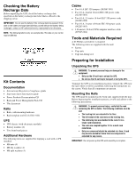
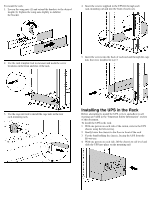
4. Turn on the battery circuit breaker. Connecting the Communications Port The UPS includes a communications port that allows the unit to exchange data with the host computer. IMPORTANT: Power management software requires the communications port to be appropriately cabled to the host computer. Connect the UPS/computer interface cable (295245-004) from the communications port on the UPS to the appropriate communications port on the host computer. CAUTION: Use only the specific cable supplied with the UPS to connect the communications port to the host computer. NOTE: If optional extended runtime modules (ERMs) are attached, place the ERM battery circuit breakers in the On position after the UPS circuit breaker is placed in the On position. 5. Attach the front bottom bezel (1) using the two captive screws on each side (2). Installing Extended Runtime Modules WARNING: To prevent personal injury or damage to the equipment, the ERMs must be installed by a trained service technician. The ERM can be connected directly to an R6000 model or to another ERM. Up to two ERM units can be connected. Depending on the load, one ERM can extend the available UPS runtime by up to 15 minutes. A second ERM can provide runtimes up to 30 minutes at recommended loads. Powering Up the UPS Turning on the Main Circuit Breaker After a licensed electrician has the UPS properly wired to utility power, turn on the AC mains at the service panel circuit. The UPS automatically initiates a self-test. If the self-test is completed successfully, the UPS enters Standby mode, designated by the blinking green LED. If the self-test is not completed successfully, refer to the user guide for more information.
-
 1
1 -
 2
2 -
 3
3 -
 4
4 -
 5
5 -
 6
6 -
 7
7 -
 8
8
 |
 |
