HP KVM CAT5 0x1x8 HP IP Console Switchwith Virtual Media Installation Instruct - Page 2
Installation checklist, Console switch kit contents, Required items not included, Optional item - kvm switch
 |
View all HP KVM CAT5 0x1x8 manuals
Add to My Manuals
Save this manual to your list of manuals |
Page 2 highlights
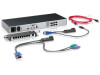
Installation checklist Before installation, refer to the following lists to be sure that all of the listed components were received. Console switch kit contents • Console switch • Power cords • Rack mounting kit • Serial cable • Documentation kit This kit might contain extra hardware for your convenience. Required items not included • Interface adapters One interface adapter is needed for each server or device. • USB 2.0 with Virtual Media • PS2 with Virtual Media • USB (not Virtual Media capable) • PS2 (not Virtual Media capable) • Serial • HP Bladesystem CAT5 KVM (not Virtual Media capable) • UTP CAT5 cable (CAT6 and CAT7 can also be used) Optional item Expansion module (not Virtual Media capable) Required tools The following tools are required for some procedures: • Phillips screwdriver • Cage nut insertion tool (included with your original rack hardware kit) Rack-mounting the console switch NOTE: Before installing the HP IP Console Viewer with Virtual Media into the rack, connect the HP IP Console Viewer with Virtual Media to a power source, using the power cords provided, and power on the unit. An activity indicator light is displayed after a few seconds. If the activity indicator light does not display, be sure that the power is on, the power cord is connected, and the power source is valid. Several rack-mounting configurations include: • Side-mount • Type A-Square- and round-hole rails • Type B-Square-hole rails NOTE: The HP IP Console Viewer with Virtual Media cannot be side-mounted into a rack with round-hole rails. • Standard-mount • Cantilever-mount • Type A-Round-hole rails • Type B-Square-hole rails
-
 1
1 -
 2
2 -
 3
3 -
 4
4 -
 5
5
 |
 |
