HP Chromebook 11 G6 EE Maintenance and Service Guide - Page 37
System board, Remove the system board
 |
View all HP Chromebook 11 G6 EE manuals
Add to My Manuals
Save this manual to your list of manuals |
Page 37 highlights
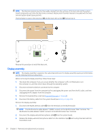
System board NOTE: All system board spare part kits include a processor, an on-board Intel 7265ac 2×2 + Bluetooth 4.2 (non-VPro) WLAN module, system memory, eMMC storage, the Google Chrome operating system, and replacement thermal material. Description Equipped with an Intel Celeron N3450 1.10-GHz (turbo up to 2.20-GHz) quad core processor (2400-MHz, 2.0-MB L2 cache, 6.0-W), an Intel graphics subsystem with UMA video memory, 8-GB of system memory, and 64-GB of eMMC storage Equipped with an Intel Celeron N3450 1.10-GHz (turbo up to 2.20-GHz) quad core processor (2400-MHz, 2.0-MB L2 cache, 6.0-W), an Intel graphics subsystem with UMA video memory, 8-GB of system memory, and 32-GB of eMMC storage Equipped with an Intel Celeron N3450 1.10-GHz (turbo up to 2.20-GHz) quad core processor (2400-MHz, 2.0-MB L2 cache, 6.0-W), an Intel graphics subsystem with UMA video memory, 4-GB of system memory, and 32-GB of eMMC storage Equipped with an Intel Celeron N3350 1.10-GHz dual core processor (2400-MHz, 2.0-MB L2 cache, 6-W), an Intel graphics subsystem with UMA video memory, 8-GB of system memory, and 64-GB of eMMC storage Equipped with an Intel Celeron N3350 1.10-GHz dual core processor (2400-MHz, 2.0-MB L2 cache, 6-W), an Intel graphics subsystem with UMA video memory, 8-GB of system memory, and 32-GB of eMMC storage Equipped with an Intel Celeron N3350 1.10-GHz dual core processor (2400-MHz, 2.0-MB L2 cache, 6-W), an Intel graphics subsystem with UMA video memory, 4-GB of system memory, and 32-GB of eMMC storage Equipped with an Intel Celeron N3350 1.10-GHz dual core processor (2400-MHz, 2.0-MB L2 cache, 6-W), an Intel graphics subsystem with UMA video memory, 4-GB of system memory, and 16-GB of eMMC storage Spare part number L15856-001 L15855-001 L15854-001 L15853-001 L15852-001 L15851-001 L15850-001 Before removing the system board, follow these steps: 1. Shut down the computer. If you are unsure whether the computer is off or in Hibernation, turn the computer on, and then shut it down through the operating system. 2. Disconnect all external devices connected to the computer. 3. Disconnect the power from the computer by first unplugging the power cord from the AC outlet, and then unplugging the AC adapter from the computer. 4. Remove the bottom cover (see Keyboard/top cover on page 20). 5. Remove the keyboard/top cover (see Keyboard/top cover on page 20). 6. Disconnect the battery cable from the system board (see Battery on page 25). When replacing the system board, be sure to remove the heat sink (see Heat sink on page 33) from the defective system board and install it on the replacement system board. Remove the system board: 1. Release the two ZIF connectors (1) to which the USB port board cables are connected, and then disconnect the USB port board cables from the system board. 2. Disconnect the display webcam/microphone cable (2) from the system board. 3. Release the adhesive strip (3) that secures the display panel cable to the system board. Component replacement procedures 31
-
 1
1 -
2
-
3
-
4
-
5
-
6
-
7
-
8
-
9
-
10
-
11
-
12
-
13
-
14
-
15
-
16
-
17
-
18
-
19
-
20
-
21
-
22
-
23
-
24
-
25
-
26
-
27
-
28
-
29
-
30
-
31
-
 32
32 -
 33
33 -
 34
34 -
 35
35 -
 36
36 -
 37
37 -
 38
38 -
 39
39 -
 40
40 -
 41
41 -
 42
42 -
43
-
44
-
45
-
46
-
47
-
48
-
49
-
50
-
51
-
52
-
53
 |
 |
