Harman Kardon AVR 254 Owners Manual - Page 31
Step Ten - Install a Multizone System, Step Eleven - Turn On the AVR 254 - not working
 |
View all Harman Kardon AVR 254 manuals
Add to My Manuals
Save this manual to your list of manuals |
Page 31 highlights
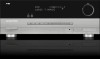
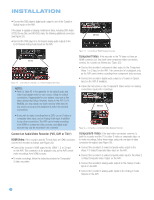
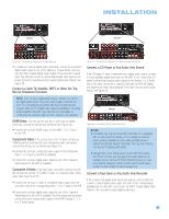
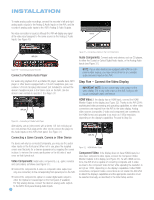
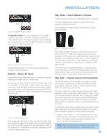
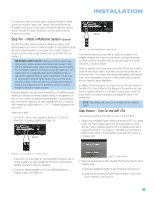
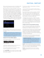
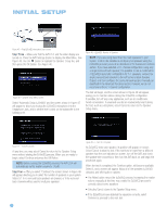
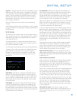
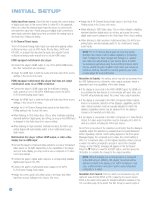
INSTALLATION To control more than one source device using the Remote IR Output, connect all sources in "daisy chain" fashion, with the AVR's Remote IR Output connected to the first device's Remote IR Input, the second device's Remote IR Output connected to the next device's Remote IR Input, and so forth. Step Ten - Install a Multizone System (Optional) The AVR 254 offers several methods of distributing music to other listening areas in your home. A multizone system is not required to enjoy the home theater experience. If you prefer not to install a multizone system at this time, skip to Step Eleven to turn on the AVR 254 and configure it. IMPORTANT SAFETY NOTE: Installing a multizone system typically requires running various cables inside walls. Always comply with the appropriate safety codes when installing concealed wiring. The AVR 254's multizone connections should be installed per the requirements of all applicable state and local building codes, as well as NEC (National Electrical Code) requirements. Failure to do so may present a potential safety hazard. If you have any doubt about your ability to work with electrical and telecommunications wiring, you are advised to hire a licensed electrician or custom installer to install the multizone system. Multizone operation uses the Surround Back/Zone 2 amplifier channels, whether you connect the remote speakers directly to the speaker outputs, or if you connect an optional external amplifier to the preamp outputs. This limits the system in the main listening room to 5.1 channels, which means you cannot listen to 6.1- or 7.1-channel programs in the main room. Select one or both: 1. Connect the remote room's speakers directly to the Surround Back/Zone 2 Speaker Outputs. See Figure 39. AVR 254 AVR 254 Figure 40 - Surround Back/Multiroom Preamp Outputs This method requires you to provide an additional component: the amplifier. However, this method may be used to increase the number of remote rooms in the system when you are also using the Surround Back/Zone 2 Speaker Outputs. Place the amplifier in the same room as the AVR 254 so that a shorter length of interconnect cable is used with a long run of speaker wire to the remote room. This is better than placing the amplifier in the remote room, which necessitates a long run of interconnect cable that would then be subject to signal degradation. In addition to the audio signal, you may connect an IR control device to the AVR 254's Zone IR Input so that listeners in the remote room may turn the multizone system on or off, select a source input, control the source device connected to that input and adjust the volume in the remote zone. NOTE: Only analog audio sources are available to the multizone system. Step Eleven - Turn On the AVR 254 Two steps are required the first time you turn on the AVR 254. 1. Gently press the Master Power Switch until the word OFF is no longer visible. The Power Indicator above the two power switches should light up in amber, indicating that the AVR is in Standby mode and is ready to be turned on. See Figure 41. Normally, you may leave the Master Power Switch in the ON position, even when the receiver is not being used. Figure 39 - Surround Back/Zone 2 Speaker Outputs If you prefer not to purchase an external amplifier to power a pair of remote speakers, you may reassign the AVR 254's Surround Back amplifier channels to power the speakers. 2. Connect an external amplifier to the Surround Back/Multiroom Preamp Outputs. See Figure 40. Figure 41 - Power Switches 2. There are several ways in which the AVR 254 may be turned on from Standby mode. a) Press the Standby/On Switch on the front panel. See Figure 41. b) Using the remote, press the AVR Power On Button or any of the Source Selectors. See Figure 42. 31
-
 1
1 -
2
-
3
-
4
-
5
-
6
-
7
-
8
-
9
-
10
-
11
-
12
-
13
-
14
-
15
-
16
-
17
-
18
-
19
-
20
-
21
-
22
-
23
-
24
-
25
-
 26
26 -
 27
27 -
 28
28 -
 29
29 -
 30
30 -
 31
31 -
 32
32 -
 33
33 -
 34
34 -
 35
35 -
 36
36 -
37
-
38
-
39
-
40
-
41
-
42
-
43
-
44
-
45
-
46
-
47
-
48
-
49
-
50
-
51
-
52
-
53
-
54
-
55
-
56
-
57
-
58
-
59
-
60
-
61
-
62
-
63
-
64
-
65
-
66
-
67
-
68
-
69
-
70
-
71
-
72
-
73
-
74
-
75
-
76
 |
 |