Gigabyte GZ-FA2CA-AJB User Manual - Page 11
Basic casing power switch control cable kit
 |
View all Gigabyte GZ-FA2CA-AJB manuals
Add to My Manuals
Save this manual to your list of manuals |
Page 11 highlights
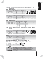
English 4-4.2 Insert the IEEE 1394 connector into the corresponding socket on the motherboard. IEEE 1394 connector A Pin Definition Pin Definition 1 TPA+ 6 TPB- A 2 TPA- 7 3 GND 8 +12V 4 GND 9 5 TPB+ 10 +12V GND B C IEEE 1394 connector B Pin Definition Pin 1 TPA+ 6 2 TPA- 7 3 GND 8 4 GND 9 5 TPB+ 10 Definition TPB+12V +12V GND IEEE 1394 connector C Pin Definition Pin 1 +12V 9 2 +12V 10 3 TPA+ 11 4 TPA- 12 5 GND 13 6 GND 14 7 TPB+ 15 8 TPB- 16 Definition +12V +12V TPA1+ TPA1GND TPB1+ TPB1- 4-4.3 Insert the Audio connector into the corresponding socket on the motherboard. HD AUDIO Pin Definition Pin Definition 1 MIC2_L 6 FSENSE1 2 GND 7 FAUDIO_JD 3 MIC2_R 8 4 -ACZ_DET 9 LINE2_L 5 LINE2_R 10 FSENSE2 AC'97 Pin Definition Pin 1 MIC 6 2 GND 7 3 MIC Power 8 4 NC 9 5 Line Out(R) 10 Definition NC NC Line Out(L) NC (2) Basic casing power switch control cable kit Follow the connectors list below for installation (see figure below) Connector Reset SW Power SW H.D.D. LED Color Green(+) / Wite(-) Orange(+) / White(-) Red(+) / White(-) Different Motherboards have different installation areas, specifications, screw holes and connectors. Please read the motherboard user manual supplied by the motherboard manufacturer. 11
-
 1
1 -
2
-
3
-
4
-
5
-
 6
6 -
 7
7 -
 8
8 -
 9
9 -
 10
10 -
 11
11 -
 12
12 -
 13
13 -
 14
14
 |
 |
