Gigabyte G250-G50 Manual - Page 41
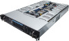
Rear System Button and LEDs
 |
View all Gigabyte G250-G50 manuals
Add to My Manuals
Save this manual to your list of manuals |
Page 41 highlights
3-4 Rear System Button and LEDs 1 2 356 7 No. Name Power button 1. and LED 2. ID Button and LED 3. Reset Button 4. NMI button 5. System Status LED 6. LAN1 Active/ Link LED 7. LAN2 Active/ Link LED Color Green Green N/A Blue N/A Green Amber N/A Green N/A Green N/A 4 Status Solid On Blink Off Solid On Off Solid On Solid On Off Solid On Blink Off Solid On Blink Off Critical Event Description N/A System is powered on N/A System is in ACPI S1 state (sleep mode) • System is not powered on or in ACPI S5 N/A • state (power off) System is in ACPI S4 state (hibernate mode) N/A System identification is active. N/A System identification is disabled. Press the button to reset the system. Press the button server generates a NMI to the processor if the multiple-bit ECC errors occur, which effectively halt the server. N/A Running or normal operation There is at least one sensor that has critical alter.When the LED is solid on, check the following: Yes • Power module failure • System fan failure • Power supply voltage issue • System temperature/voltage issue N/A System is not ready. N/A Link between system and network or no access N/A Data transmission or receiving is occurring N/A No data transmission or receiving is occurring N/A Link between system and network or no access N/A Data transmission or receiving is occurring N/A No data transmission or receiving is occurring Hardware Installation - 41 -
-
 1
1 -
2
-
3
-
4
-
5
-
6
-
7
-
8
-
9
-
10
-
11
-
12
-
13
-
14
-
15
-
16
-
17
-
18
-
19
-
20
-
21
-
22
-
23
-
24
-
25
-
26
-
27
-
28
-
29
-
30
-
31
-
32
-
33
-
34
-
35
-
 36
36 -
 37
37 -
 38
38 -
 39
39 -
 40
40 -
 41
41 -
 42
42 -
 43
43 -
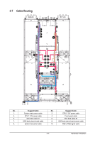 44
44 -
 45
45 -
 46
46 -
47
-
48
-
49
-
50
-
51
-
52
-
53
-
54
-
55
-
56
-
57
-
58
-
59
-
60
-
61
-
62
-
63
-
64
-
65
-
66
-
67
-
68
-
69
-
70
-
71
-
72
-
73
-
74
-
75
-
76
-
77
-
78
-
79
-
80
-
81
-
82
-
83
-
84
-
85
-
86
-
87
-
88
-
89
-
90
-
91
-
92
-
93
-
94
-
95
-
96
-
97
-
98
-
99
-
100
-
101
-
102
-
103
-
104
-
105
-
106
-
107
-
108
-
109
-
110
-
111
-
112
-
113
-
114
-
115
-
116
-
117
-
118
-
119
-
120
-
121
-
122
-
123
-
124
-
125
-
126
-
127
-
128
-
129
-
130
-
131
-
132
-
133
 |
 |
