GE UVB36DKBB Quick Specs - Page 1
GE UVB36DKBB Manual
 |
View all GE UVB36DKBB manuals
Add to My Manuals
Save this manual to your list of manuals |
Page 1 highlights
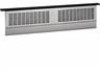
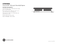
8-1/2" UVB36DK 2-1/8"* Universal 36" Telescopic Downdraft System DIMENSIONS AND INSTALLATION INFORMATION (IN INCPHREOSDPU)RCOTDDUICMTEDNISMIOENSIONS A AB B NOTE: Telescopic downdraft vents are not 36" Mo3d6e" lMs odel3s6" 3336-"153/136-1" 5/16" recommended to be installed with cooktops that are flush mounted. Approved for use with the following8-M1/2o"n8-o1g/2r"am, GE Profile™ Series and GE® Series cooktops-36" electric models, 36" gas-sealed burner models 2-a1n/8d"2*-316/8""*induction models. 36" 36" 33-153/136-1" 5/16" *Minimum distance required between the back edge of the cooktop and the back2o"f the2c"utout in the countertop 1-1/2"1-1/2" 8-1/2"8-1/2" Lift Lift 2-1/4"2-1/4" NOT APPROVED FOR USE WITH S3T6"AN36D" ARD BURNER GAS COOKTOPS. 23-5/82"3-5/8" 9-1/2"9-1/2" 32-3/83"2-3/8" NOTE: The cooktop must be at least 26" deep with a flat surface area of 23-1/2" or more, front to back. In addition, other clearances to the front edge of the countertop must be considered. 36" 29-1/2" 36" 1 33-15/16" 2 23-5/8" Locate the Gas or Electrical Connection Only Within the Shaded Area DO NOT Locate Gas or Electrical Connections within this Area Electrical 12" Outlet 12" Above Cabinet Floor PRODUCT DIMENSIONS PRODUCT DIAMENSIONBS 36" Models 3A6" 33B-15/16" 36" Models 36" 33-15/16" UVB36SK_DK N*MOinTim*EMu:minDimdiimsutmaenndcisesitoraennqcsueirsrehedqobuweirtnewdaeberenetwfoeernreference only. Btaehnfedobrtahetachenkcebduebatdtachtgkceiekonboefagfdtchtgokheeuoecoftcuftotchtoohoeukeucttocunpottooeukrtttoopp, refer to instructions piancthkeeidcnotwuhneittcehortuodnpotewrtnodp raft and cooktop. LocateLotchaetGe athseorGEalsecotrriEclaelctrical ConneCcotnionneOctniolynWOinthlyinWthitehin the ShadeSdhAadreead Area 2-1/8"* 8-1/2" 8-1/2" 36" 36" NOTE: Installation on cabinets/countert2o9-1p/2s" against DO NOT LDoOcaNtOeT Locate 2-1/8"* 29-1/GC2oa" nsnoercEtliGCeocoantnssrniowceraictElhtlieioncntsriwcaitlhin 36" the wall will not be possible in most applicationthsis.Areathis Area Against the wall installations are limited to 36" dimension requirements. Refer to installation 12" 12" ElectriEclaelctrical OutletO1u2t"let 12" instructions packed with product for further details. AboveAbove CabinCetabinet JXRB67 INDOOR REMOTE ACCESSORY. Floor Floor Optional accessory may be ordered for installation of motor and blower assembly in an indoor remote *Minimum distance required between the back edge of the cooktop and the back of the cutout 33-15/16" 33-15/16" 23-5/8" 23-5/8" Locate the Gas or Electrical Connection Only Within the Shaded Area location. in the countertop *Minimum distance required between UVBU3V6BSK36_DSKK_DthKe back edge of the cooktop and the back of the cutout in the countertop For answers to your Monogram, GE Profile™ Series 29-1/2" 29-1/2" Locate DO NOT Locate Gas or Electrical the Gas or Electrical Connection Connections within this Area Only Within the Shaded Area DO NOT Locate Gas or Electrical Connections within this Area Electrical 12" Outlet 12" Above Cabinet Floor or GE® Series appliance questions, visit our website at geappliances.com or call GE Answer Center service, 800.626.2000. 12" UVB36SK_DK Electrical SpecifOAicbautotilovenet C1r2e"ated 10/15 Cabinet Floor 2" 1-1/2" 1-1/ 2-1/4" 2-1/ 9-1/2" 9-1
-
 1
1 -
 2
2 -
 3
3
 |
 |
