GE JVX5305EJES Use and Care Manual - Page 16
To install to the bottom of cabinet
 |
View all GE JVX5305EJES manuals
Add to My Manuals
Save this manual to your list of manuals |
Page 16 highlights
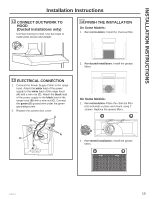
INSTALLATION PREPARATION Installation Preparation 2 PREPARING MOUNTING (Cont) B To install to the bottom of cabinet Use the diagram or hood as a template and mark the locations on the cabinet for the keyholes screws. Drive the 4 (F) screws partway into the bottom of the cabinet (or wood shims). Hood mounting screws (4) Cabinet front Cabinet 24" 30" 36" X 10 3»4" 13 3»4" 16 3»4" X Cabinet Bottom 10 1»4" 2 1»2" Wood shims (recessed-bottom cabinets only) Center line 3 PREPARE FOR ELECTRICAL AND VENTING Select the vent option that your installation will require and proceed to that section: A Outside top exhaust (Vertical duct-3 1»4" x 10" Rectangular) • Use the diagram as a template and mark the locations on the cabinet for ductwork and electrical wiring. Cabinet front Cabinet Bottom 7 1»2" 4" 1»2" 5 1»4" 5 1»4" Vertical duct access hole ø1 1»4" 3»4" Center line Electrical access hole (in cabinet bottom) B Outside top exhaust (Vertical duct-7" Round) • Use the diagram as a template and mark the locations on the cabinet for ductwork and electrical wiring. Cabinet front Cabinet Bottom Access hole for 7" round duct 7 1»2" 8" DIA. HOLE ø1 1»4" 3»4" 4 1»4" Center line Electrical access hole (in cabinet bottom) C Outside rear exhaust (Horizontal duct-3 1»4" x 10" Rectangular) • Use the diagram as a template and mark the locations on the cabinet for ductwork and electrical wiring. Cabinet Front 3»4" 3»4" 4 1»4" Cabinet Bottom 5 1»4" ø1 1»4" 5 1»4" 7 1»2" Electrical access hole (in wall) Center line 16 49-80783-3
-
 1
1 -
2
-
3
-
4
-
5
-
6
-
7
-
8
-
9
-
10
-
 11
11 -
 12
12 -
 13
13 -
 14
14 -
 15
15 -
 16
16 -
 17
17 -
 18
18 -
 19
19 -
 20
20 -
 21
21 -
22
-
23
-
24
-
25
-
26
-
27
-
28
-
29
-
30
-
31
-
32
-
33
-
34
-
35
-
36
-
37
-
38
-
39
-
40
-
41
-
42
-
43
-
44
-
45
-
46
-
47
-
48
 |
 |
