GE JVB67HBB Use and Care Manual - Page 8
Installation Instructions - downdraft
 |
UPC - 084691082163
View all GE JVB67HBB manuals
Add to My Manuals
Save this manual to your list of manuals |
Page 8 highlights
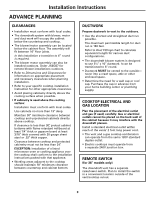
Installation Instructions ADVANCE PLANNING CLEARANCES • Installation must conform with local codes. • The downdraft system with blower, motor and duct work will occupy the cabinet below the countertop and cooktop. • The blower/motor assembly can be located below the cabinet floor. The assembly will fit between 16″ floor joists. In this installation a transition to 6 ″ round is required. • The blower motor assembly can also be installed outdoors. Order JXBC67 for remote blower installations outdoors. • Refer to Dimensions and Clearances for information on appropriate placement and necessary clearances when planning installation. • Refer to your specific cooktop installation instruction for other appropriate clearances. • Avoid placing cabinetry directly above the cooking surface when possible. • If cabinetry is used above the cooking surface: Installation must conform with local codes. Use cabinets no more than 13″ deep. Maintain 30″ minimum clearance between cooktop and unprotected cabinets directly above cooktop. If clearance is less than 30″, protect cabinet bottoms with flame-retardant millboard at least 1/4″ thick or gypsum board at least 3/16″ thick covered with 28 gauge sheet steel or .02″ thick copper. Clearance between cooktop and protected cabinetry must not be less than 24″. EXCEPTION: Installation of a listed microwave oven or cooking appliance over the cooktop shall conform to the installation instructions packed with that appliance. • Working areas adjacent to the cooktop should maintain 18″ minimum clearance between countertop and cabinet bottom. DUCTWORK Prepare ductwork to vent to the outdoors. • Use the shortest and straightest duct run possible. The maximum permissible length for duct run is 150 feet. Refer to Duct Fittings chart to calculate equivalent length for various duct configurations. • The downdraft blower system is designed to use 31⁄4″ x 10″ ductwork. It can be transitioned to 6″ round. • Ductwork MUST be vented to the outside- never into a crawl space, attic or other enclosed space. • Determine the need for a wall cap or roof cap. Purchase the cap in advance from your home building center or plumbing supply. COOKTOP ELECTRICAL AND GAS LOCATION Plan the placement of the electrical outlet and gas (if used) carefully. Gas or electrical outlets cannot be placed on the back wall of the cabinet because it may interfere with the downdraft plenum. Install a standard electrical outlet within reach of the vents' 2 foot long power cord. • The vent and a gas cooktop combination can operate from the same 120V standard duplex outlet. • Electric cooktops must operate from a separate 240V junction box. REMOTE SWITCH (for 36″ models only) The downdraft vent has a separate raise/lower switch. Plan to install the switch in a convenient location outside of the vent/cooktop cutout. 8
-
 1
1 -
2
-
 3
3 -
 4
4 -
 5
5 -
 6
6 -
 7
7 -
 8
8 -
 9
9 -
 10
10 -
 11
11 -
 12
12 -
 13
13 -
14
-
15
-
16
-
17
-
18
-
19
-
20
-
21
-
22
-
23
-
24
-
25
-
26
-
27
-
28
-
29
-
30
-
31
-
32
-
33
-
34
-
35
-
36
-
37
-
38
-
39
-
40
 |
 |
