GE DPVH890EJWW Owners Manual - Page 35
REMOVE THE DOOR ASSEMBLY, BEFORE YOU START, the chrome cover from the inner door. Put
 |
View all GE DPVH890EJWW manuals
Add to My Manuals
Save this manual to your list of manuals |
Page 35 highlights
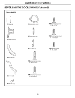
Installation Instructions BEFORE YOU START Unplug the dryer from its electrical outlet. 1 REMOVE THE DOOR ASSEMBLY (cont.) Hold the door and remove the 2 hinge screws (#10 x 0.75″ tapping screws). Pull the door away from the dryer front panel. 1 REMOVE THE DOOR ASSEMBLY Remove the side hinge cap by opening the dryer door and removing the screw from behind the hinge (#8 x .375″ tapping screw). Then using your hand, pop the hinge cap off the dryer. 1 x C Screw 2 x B Screws 2 DISASSEMBLE THE DOOR ASSEMBLY Lay the door down on a soft, protected, flat surface so that the inner part faces upward (door resting on the handle side). Remove the 7 screws (#10 x 1.125″ tapping screws) located around the perimeter of the door. 7 x A Screws Hinge cap Turn the door assembly over and separate the chrome cover from the inner door. Put the inner door aside on a soft, protected flat surface. 35
-
 1
1 -
2
-
3
-
4
-
5
-
6
-
7
-
8
-
9
-
10
-
11
-
12
-
13
-
14
-
15
-
16
-
17
-
18
-
19
-
20
-
21
-
22
-
23
-
24
-
25
-
26
-
27
-
28
-
29
-
 30
30 -
 31
31 -
 32
32 -
 33
33 -
 34
34 -
 35
35 -
 36
36 -
 37
37 -
 38
38 -
 39
39 -
 40
40 -
41
-
42
-
43
-
44
-
45
-
46
-
47
-
48
-
49
-
50
-
51
-
52
-
53
-
54
-
55
-
56
-
57
-
58
-
59
-
60
-
61
-
62
-
63
-
64
-
65
-
66
-
67
-
68
-
69
-
70
-
71
-
72
-
73
-
74
-
75
-
76
-
77
-
78
-
79
-
80
-
81
-
82
-
83
-
84
-
85
-
86
-
87
-
88
-
89
-
90
-
91
-
92
-
93
-
94
-
95
-
96
-
97
-
98
-
99
-
100
-
101
-
102
-
103
-
104
-
105
-
106
-
107
-
108
-
109
-
110
-
111
-
112
-
113
-
114
-
115
-
116
-
117
-
118
-
119
-
120
-
121
-
122
-
123
-
124
-
125
-
126
-
127
-
128
-
129
-
130
-
131
-
132
-
133
-
134
-
135
-
136
-
137
-
138
-
139
-
140
-
141
-
142
-
143
-
144
-
145
-
146
-
147
-
148
-
149
-
150
-
151
-
152
-
153
-
154
-
155
-
156
 |
 |
