Garmin Reactor 40 Mechanical/Retrofit/Solenoid Corepack Installation Instructi - Page 8
Configuration, Maintenance, Appendix
 |
View all Garmin Reactor 40 Mechanical/Retrofit/Solenoid Corepack manuals
Add to My Manuals
Save this manual to your list of manuals |
Page 8 highlights
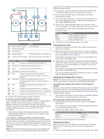
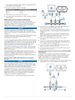
2 In the location where you plan to connect the CCU, disconnect one side of a NMEA 2000 T-connector from the network. 3 If necessary, connect a NMEA 2000 backbone extension cable (not included) to the side of the disconnected Tconnector to extend the NMEA 2000 network backbone. 4 Add an included T‑connector for the CCU to the NMEA 2000 backbone by connecting it to the side of the disconnected T‑connector or backbone extension cable. 5 Route the included drop cable to the CCU and to the bottom of the T-connector added in step 4. If the included drop cable is not long enough, you can use a drop cable up to 6 m (20 ft.) long (not included). 6 Connect the drop cable to the CCU and the T-connector. 7 If needed, repeat steps 2 through 6 for the helm control (optional) or a compatible Garmin chartplotter. Connecting Optional NMEA 2000 Devices to the Autopilot System You can use advanced features of the autopilot system by connecting optional NMEA 2000 compatible devices, such as a wind sensor or a GPS device, to the NMEA 2000 network. NOTE: You can connect optional devices that are not NMEA 2000 compatible to the helm control through NMEA 0183 (NMEA 0183 Connection Considerations, page 8). 1 Add an additional T-connector (not included) to the NMEA 2000 network. 2 Connect the optional NMEA 2000 device to the T-connector by following the instructions provided with the device. each internal port should be connected to the A (+) and B (-) wires of the NMEA 0183 device. • You can connect one NMEA 0183 device to the Rx port to input data to this chartplotter, and you can connect up to three NMEA 0183 devices in parallel to the Tx port to receive data output by this chartplotter. • See the NMEA 0183 device installation instructions to identify the transmit (Tx) and receive (Rx) wires. • You must use 28 AWG, shielded, twisted-pair wiring for extended runs of wire. Solder all connections and seal them with heat-shrink tubing. • Do not connect the NMEA 0183 data wires from this device to power ground. • The power cable from the chartplotter and the NMEA 0183 devices must be connected to a common power ground. • The internal NMEA 0183 ports and communication protocols are configured on the chartplotter. See the NMEA 0183 section of the chartplotter owner's manual for more information. • See the chartplotter owner's manual for a list of the approved NMEA 0183 sentences that the chartplotter supports. Two-Way NMEA 0183 Communication Configuration The autopilot must be configured and tuned to your boat dynamics. You can use the Dockside Wizard and the Sea Trial Wizard on the helm control or a compatible Garmin chartplotter to configure the autopilot. See the included configuration guide for more information on configuring the autopilot. Maintenance Corrosion Blocker NOTICE To ensure the long life of all parts, apply corrosion blocker to the drive unit at least twice yearly. A marine-rated corrosion blocker should be applied to the drive unit after all connections are made. Appendix NMEA 0183 Connection Diagrams The helm control is not included in all autopilot packages. A helm control must be installed in your autopilot system to connect NMEA 0183 devices according to these diagrams. If you install the autopilot without a helm control, all NMEA devices you plan to use with the autopilot system must be connected to a compatible Garmin chartplotter on the same NMEA 2000 network as the CCU. See the installation instructions provided with your chartplotter for NMEA 0183 connection information. These wiring diagrams are examples of different situations you may encounter when connecting your NMEA 0183 device to the helm control. NMEA 0183 Connection Considerations • The chartplotter provides one Tx (transmit) port and one Rx (receive) port. • Each port has 2 wires, labeled A and B according to the NMEA 0183 convention. The corresponding A and B wires of NMEA 2000 network (provides power to the helm control) 12 Vdc power source Helm control NMEA 0183 compatible device Wire Helm Control Wire Color - Function N/A N/A Blue - Tx/A (+) White - Tx/B (-) Brown - Rx/A (+) Green - Rx/B (-) NMEA 0183 Compatible Device Wire Function Power NMEA 0183 ground Rx/A (+) Rx/B (-) Tx/A (+) Tx/B (-) NOTE: When connecting a NMEA 0183 device with two transmitting and two receiving lines, you do not need to connect the NMEA 2000 bus and the NMEA 0183 device to a common ground. Only One Receiving Wire If your NMEA 0183 compatible device has only one receiving wire (Rx), you must connect it to the blue wire (Tx/A) from the helm control, and leave the white wire (Tx/B) from the helm control unconnected. 8
-
 1
1 -
2
-
 3
3 -
 4
4 -
 5
5 -
 6
6 -
 7
7 -
 8
8 -
 9
9 -
 10
10 -
 11
11 -
 12
12
 |
 |
