Garmin GT15M-TM Installation Instructions - Page 2
Installing the Transducer on a Trolling Motor
 |
View all Garmin GT15M-TM manuals
Add to My Manuals
Save this manual to your list of manuals |
Page 2 highlights
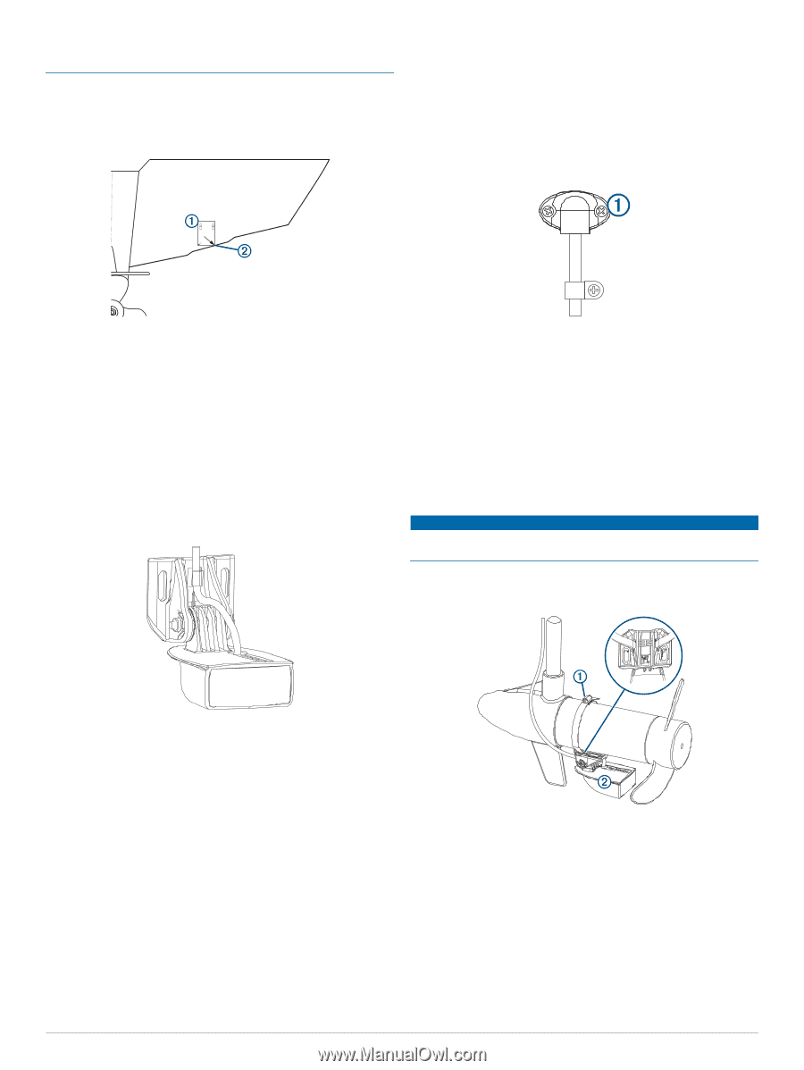
The cables connected to the transducer should not be cut, because cutting the transducer cables voids your warranty. 1 Cut out the template. 2 With the template aligned vertically on the transom at the À installation location (Mounting Location Considerations, page 1), place the bottom corner of the template on the Á edge of the transom. You should avoid routing the cable close to electrical wires or other sources of electrical interference. Installing the Cable-Entry Cover If you routed the cable through the transom after you installed the transducer, you should install the cable-entry cover to keep water from entering your boat. 1 Place the cable-entry cover over the hole and the cable, À with the opening pointing downward, and mark the location of the two pilot holes. 3 Mark the center location of the two holes of the template. 4 Remove the template from the transom. 5 Wrap a piece (7/10 in.) from of tape around the point of the a 4 bit, mm (5/32 in.) bit to avoid drilling at 18 mm the pilot holes too deep. 6 If you are installing the bracket on fiberglass, place a piece of tape over the pilot-hole location to reduce cracking of the gel coat. 7 Using the 4 18 mm (7/10 mm in.) (5/32 in.) bit, drill the deep at the marked pilot holes locations. approximately 8 Apply marine sealant to the included 20 mm screws, and attach the transducer assembly to the transom. 9 Route the cable under the transom mount cable hook. 2 Remove the cable-entry cover, and, using a bit, drill the pilot holes approximately 10 mm 3.2 (3/8 mm in.) (1/8 in.) deep. 3 Fill the pass-through hole with marine sealant so it covers the cable completely and there is excess sealant around the hole and the cable. 4 Place the cable-entry cover over the hole and the cable, with the opening pointing downward. 5 Apply marine sealant to the included 12 mm M4 screws, and attach the cable-entry cover to the transom. 6 Wipe away all excess marine sealant. Installing the Transducer on a Trolling Motor NOTICE Do not cut the transducer cable. Cutting the transducer cable will void your warranty. 1 Insert a hose clamp (not included) through the slot on the À transducer mount , until equal lengths extend on both sides Á of the mount. 10If you must route the cable through the transom, choose a pilot-hole location well above the waterline and mark it. 11Place a cable clamp on the transducer cable, approximately halfway between the transducer and the top of the transom or the pilot hole. 12Mark the pilot-hole location for the cable clamp, and using a 3.2 (3/8 mm (1/8 in.) in.) deep. bit, drill a pilot hole approximately 10 mm 13Apply marine sealant to the included 12 mm screw, and attach the cable clamp to the transom. 14If you marked a pilot hole in step 3, using a 25 mm (1 in.) drill bit, drill a pass-through hole completely through the transom. 15Route the transducer cable to the sounder: • If you are routing the cable using a pass-through hole, push it through the hole you drilled in step 12, and install the cable-entry cover (Installing the Cable-Entry Cover, page 2). • If you are not routing the cable using a pass-through hole, route the cable up and over the top of the transom. 2 Place the transducer mount against the body of the trolling motor with the narrow end of the transducer pointed away from the propeller. 3 Secure the hose clamp around the body of the trolling motor, and tighten the hose clamp. 4 Position the transducer so it is parallel to the bottom when in use. 5 Use cable ties (not included) to secure the transducer cable. 6 Route the transducer cable to the installation location of the sounder while taking these precautions. • The cable should not be routed close to electrical wires or other sources of electrical interference. 2
-
 1
1 -
 2
2 -
 3
3 -
 4
4
 |
 |