Frigidaire FRS224YS2 Installation Instructions (All Languages) - Page 6
Fixing the Installation Plate, Drilling the Hole - refrigerator parts
 |
View all Frigidaire FRS224YS2 manuals
Add to My Manuals
Save this manual to your list of manuals |
Page 6 highlights
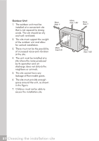
B 0.2"-0.28" Indoor unit outline 6" or more from the wall 1.97'' Refrigerant pipe hole (right) Ø 2.56" 3.94'' 6" or more from the ceiling A Installation plate =21500 Btu's (A:39.69" B:12.40") 6" or more from the wall 1.97'' Refrigerant pipe hole (right) Ø 2.56" 4.88'' Fixing the Installation Plate 1. Install the installation plate horizontally over the structural parts on the wall using the spaces indicated on the plate, as shown in the figures above. 2. In the case of tiled, concrete or similar walls, create 0.2" diameter holes. Place anchorage supports for the appropriate assembly screws. 3. Fix the installation plate to the wall with eight A type screws. 4. At all times securing to the wall studs is recommended. Attention Fit the Installation Plate and drill holes in the wall according to the wall structure and corresponding mounting points on the installation plate (Dimensions are in "mm" unless otherwise stated). Installation plate Drilling the Hole Wall 1. Determine the position of the hole for the pipes using the Indoor unit installation plate and drill the pipe hole so that it is tilted slightly downward. 2. Always use a pipe cover with an opening when drilling. Outdoor unit 11 Indoor unit installation
-
 1
1 -
 2
2 -
 3
3 -
 4
4 -
 5
5 -
 6
6 -
 7
7 -
 8
8 -
 9
9 -
 10
10 -
 11
11 -
 12
12 -
13
-
14
-
15
-
16
-
17
-
18
-
19
-
20
-
21
 |
 |
