Frigidaire FRS184YS2 Installation Instructions (All Languages) - Page 3
Parts list
 |
View all Frigidaire FRS184YS2 manuals
Add to My Manuals
Save this manual to your list of manuals |
Page 3 highlights
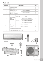
Parts list NUMBER 1 2 3 4 PART NAME Installation plate Drain Joint Self-tapping scr ew A #7 X 1" Remote controller capacity < 18000 Btu's capacity > 24000 Btu's Liquid side Connecting Ø1/4" 5 pipe Ø3/8" (capacity < 12000 Btu's) assembly Gas side Ø1/2" (capacity < 18000 Btu's) Ø5/8" (capacity > 24000 Btu's) Drainage 6 Plug capacity = 18000 Btu's capacity = 21500 Btu's 7 Remote Controller holder 8 Self-tapping screw B #4 X 3/8" QTY. 1 1 5 10 1 1 3 2 1 2 Indoor unit 6 4 2 8 7 1 3 Outdoor unit Parts list 08
-
 1
1 -
 2
2 -
 3
3 -
 4
4 -
 5
5 -
 6
6 -
 7
7 -
 8
8 -
 9
9 -
10
-
11
-
12
-
13
-
14
-
15
-
16
-
17
-
18
-
19
-
20
-
21
 |
 |

Parts list
3
1
4
Indoor unit
Outdoor unit
Parts list
PART NAME
Installation plate
Drain Joint
QTY.
1
2
3
4
1
1
1
Remote controller
Connecting
pipe
assembly
Liquid side
Gas side
NUMBER
(capacity < 18000 Btu's)
(capacity < 12000 Btu's)
(capacity > 24000 Btu’s
)
Ø1/4"
Ø1/2"
Ø3/8"
Ø5/8"
Self-tapping scr
ew A
#
7
X
1"
5
08
Drainage
Plug
6
capacity
= 18000 Btu's
capacity
= 21500 Btu s
3
2
capacity < 18000 Btu's
capacity > 24000 Btu’s
5
10
6
8
7
'
7
8
Remote Controller holder
1
2
Self-tapping screw B
#
4
X
3/8"
2
1